 |
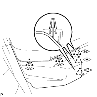
Using a clip remover, remove the 2 clips <A>.
COMBINATION METER > REMOVAL |
| 1. PRECAUTION |
| 2. REMOVE FRONT FLOOR COVER RH |
|
Using a clip remover, remove the 2 clips <A>.
Disengage the 3 clips <B>.
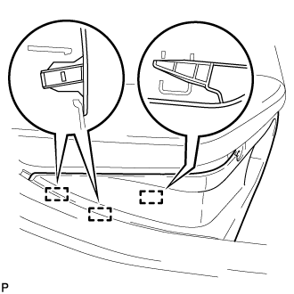 |
Disengage the 3 guides and remove the front floor cover RH.
| 3. DISCONNECT CABLE FROM NEGATIVE AUXILIARY BATTERY TERMINAL |
| 4. REMOVE CENTER INSTRUMENT CLUSTER FINISH PANEL SUB-ASSEMBLY |
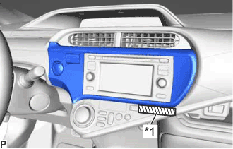 |
Apply protective tape to the area shown in the illustration.
| *1 | Protective Tape |
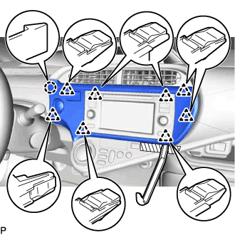 |
Using a moulding remover, disengage the 8 clips and claw.
Disconnect the connector and remove the center instrument cluster finish panel sub-assembly.
| 5. REMOVE NO. 2 INSTRUMENT PANEL REGISTER ASSEMBLY (for LHD) |
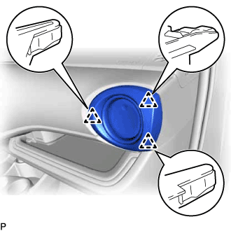 |
Disengage the 3 clips and remove the No. 2 instrument panel register assembly.
| 6. REMOVE NO. 1 INSTRUMENT PANEL REGISTER ASSEMBLY (for RHD) |
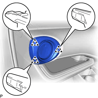 |
Disengage the 3 clips and remove the No. 1 instrument panel register assembly.
| 7. REMOVE INSTRUMENT CLUSTER FINISH PANEL GARNISH |
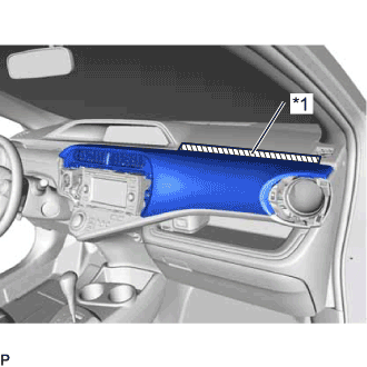 |
Apply protective tape to the area shown in the illustration.
| *1 | Protective Tape |
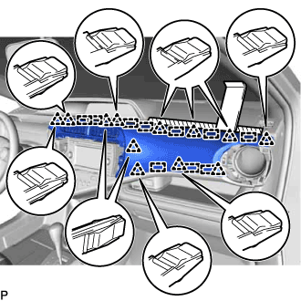 |
Using a moulding remover, disengage the 12 clips and 10 guides to remove the instrument cluster finish panel garnish.
| 8. REMOVE CENTER INSTRUMENT PANEL REGISTER ASSEMBLY |
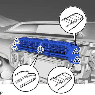 |
Disengage the claw and 4 clips to remove the center instrument panel register assembly.
| 9. REMOVE INSTRUMENT CLUSTER FINISH PANEL SUB-ASSEMBLY |
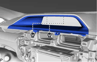 |
Using a clip remover, remove the 2 clips.
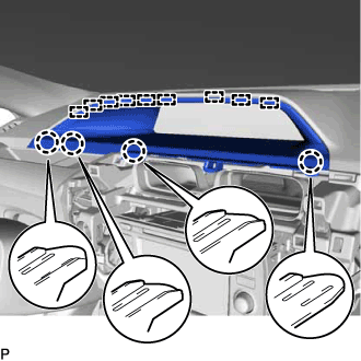 |
Disengage the 4 claws and 9 guides and remove the instrument cluster finish panel sub-assembly.
| 10. REMOVE COMBINATION METER ASSEMBLY |
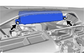 |
Remove the 2 screws.
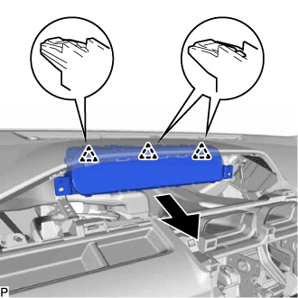 |
Disengage the 3 clips as shown in the illustration.
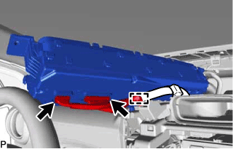 |
Disconnect the 2 connectors.
Disengage the clamp and remove the combination meter assembly.