 |
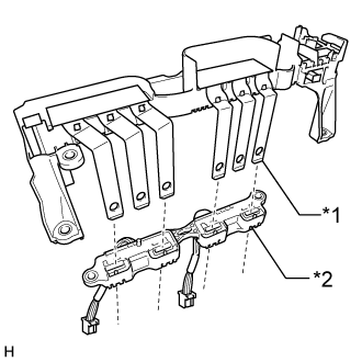
Insert the bus-bars of the inverter terminal sub-assembly into the inverter current sensor sub-assembly as shown in the illustration.
| *1 | Bus-bar |
| *2 | Inverter current sensor sub-assembly |
INVERTER CURRENT SENSOR > REASSEMBLY |
| 1. INSTALL INVERTER CURRENT SENSOR SUB-ASSEMBLY |
|
Insert the bus-bars of the inverter terminal sub-assembly into the inverter current sensor sub-assembly as shown in the illustration.
| *1 | Bus-bar |
| *2 | Inverter current sensor sub-assembly |
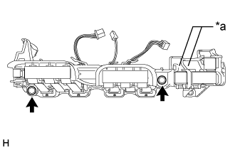 |
Install the inverter current sensor sub-assembly with the 2 bolts.
| *a | Terminal Tray |
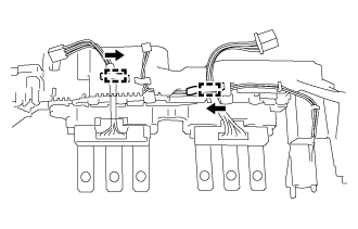 |
Engage the wire harness of inverter current sensor sub-assembly to the 2 clamps as shown in the illustration.
Remove the protective tape.
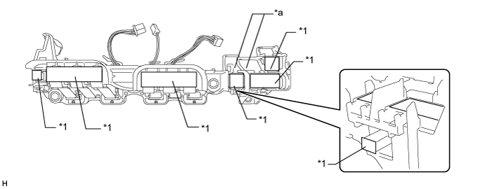
| *1 | Protective Tape | - | - |
| *a | Terminal Tray | - | - |