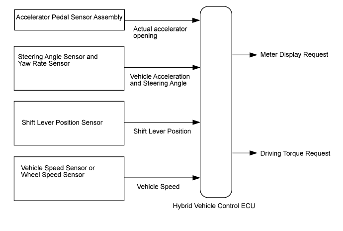
HYBRID CONTROL SYSTEM > Drive Start Control System |
| 1.SYMPTOM CONFIRMATION |
Interview the customer to confirm the problem.
| Result | Proceed to |
| Hunting | A |
| Hesitation/poor acceleration | B |
|
| ||||
| A | |
 |
| 2.PAST ACTIVATION CONFIRMATION |
Check if the customer operated the vehicle in a way that would cause the drive start control to operate.
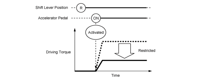
Condition 1 (Reverse control)
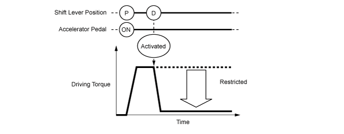
Condition 2 (Shift control A)
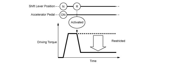
Condition 3 (Shift control B)
| Result | Proceed to |
| Performed | A |
| Not performed | B |
|
| ||||
| A | |
|
| 3.CHECK DTC OUTPUT |
Connect the intelligent tester to the DLC3.
Turn the power switch on (IG).
Enter the following menus: System Select / Utility / All Codes.
Check for DTCs.
| Result | Proceed to |
| No DTCs are output. | A |
| DTCs are output | B |
Turn the power switch off.
|
| ||||
| A | |
|
| 4.READ VALUE USING INTELLIGENT TESTER (FR, FL, RR, RL WHEEL SPEED) |
Connect the intelligent tester to the DLC3.
Turn the power switch on (READY).
Enter the following menus: Chassis / ABS/VSC/TRC / Data List / FR Wheel Speed, FL Wheel Speed, RR Wheel Speed and RL Wheel Speed.
Read the value displayed on the intelligent tester.
| Tester Display | Measurement Item / Range | Normal Condition |
| FR Wheel Speed | Front speed sensor RH Min.: 0 km/h (0 mph), Max.: 326 km/h (202 mph) | When driving at constant speed: No large fluctuations |
| FL Wheel Speed | Front speed sensor LH Min.: 0 km/h (0 mph), Max.: 326 km/h (202 mph) | When driving at constant speed: No large fluctuations |
| RR Wheel Speed | Rear speed sensor RH Min.: 0 km/h (0 mph), Max.: 326 km/h (202 mph) | When driving at constant speed: No large fluctuations |
| RL Wheel Speed | Rear speed sensor LH Min.: 0 km/h (0 mph), Max.: 326 km/h (202 mph) | When driving at constant speed: No large fluctuations |
| Tester Display | Condition | Specified Condition |
| FR Wheel Speed FL Wheel Speed RR Wheel Speed RL Wheel Speed | Vehicle stopped, engine running | 0 km/h (0 mph) |
| Vehicle being driven at constant speed between 16 to 64 km/h (10 to 40 mph) | No large fluctuations when driving at a constant speed |
Turn the power switch off.
|
| ||||
| OK | |
|
| 5.READ VALUE USING INTELLIGENT TESTER (VEHICLE SPD) |
Connect the intelligent tester to the DLC3.
Turn the power switch on (READY).
Enter the following menus: Powertrain / Hybrid Control / Data List / Vehicle Spd.
Read the value displayed on the intelligent tester.
| Tester Display | Condition | Specified Condition |
| Vehicle Spd | Vehicle stopped | 0 km/h (0 mph) |
| Vehicle being driven at a constant speed (16 to 64 km/h (10 to 40 mph)) | No large fluctuations in displayed speed |
Turn the power switch off.
|
| ||||
| OK | |
|
| 6.READ VALUE USING INTELLIGENT TESTER (DECELERATION SENSOR) |
Connect the intelligent tester to the DLC3.
Turn the power switch on (READY).
Enter the following menus: Chassis / ABS/VSC/TRC / Data List / Deceleration Sensor and Deceleration Sensor2.
Read the value displayed on the intelligent tester.
| Tester Display | Condition | Specified Condition |
| Deceleration Sensor Deceleration Sensor2 | During deceleration | Value changes with vehicle speed |
| During acceleration | Value changes with vehicle speed |
Turn the power switch off.
|
| ||||
| OK | |
|
| 7.READ VALUE USING INTELLIGENT TESTER (STEERING ANGLE SENSOR) |
Connect the intelligent tester to the DLC3.
Turn the power switch on (READY).
Enter the following menus: Chassis / ABS/VSC/TRC / Data List / Steering Angle Sensor.
Read the value displayed on the intelligent tester.
| Tester Display | Measurement Item / Range | Normal Condition |
| Steering Angle Sensor | Steering angle sensor Min.: -3276.8 degrees, Max.: 3276.7 degrees | Turning left: Increases Turning right: Decreases |
| Tester Display | Condition | Specified Condition |
| Steering Angle Sensor | Steering wheel turned left | Value increases with steering wheel operation |
| Steering wheel turned right | Value decreases with steering wheel operation |
Turn the power switch off.
|
| ||||
| OK | ||
 | ||
| ||
| 8.PAST ACTIVATION CONFIRMATION |
Check if the customer operated the vehicle in a way that would cause the drive start control to operate.
Condition 1 (Reverse control)
Condition 2 (Shift control A)
Condition 3 (Shift control B)
| Result | Proceed to |
| Not performed | A |
| Performed | B |
|
| ||||
| A | |
|
| 9.CHECK DTC OUTPUT |
Connect the intelligent tester to the DLC3.
Turn the power switch on (IG).
Enter the following menus: System Select / Utility / All Codes.
Check for DTCs.
| Result | Proceed to |
| No DTCs are output. | A |
| DTCs are output | B |
Turn the power switch off.
|
| ||||
| A | |
|
| 10.INSPECT SHIFT LEVER POSITION SENSOR |
Inspect the shift lever position sensor (Click here).
|
| ||||
| A | |
|
| 11.READ VALUE USING INTELLIGENT TESTER (ACCEL PEDAL POS #1, ACCEL PEDAL POS #2) |
Connect the intelligent tester to the DLC3.
Turn the power switch on (IG).
Enter the following menus: Powertrain / Hybrid Control / Data List / Accel Pedal Pos #1, Accel Pedal Pos #2.
Read the value displayed on the intelligent tester.
| Tester Display | Measurement Item / Range | Normal Condition |
| Accel Pedal Pos #1 | Accelerator pedal position sensor No. 1 (Sensor voltage is multiplied by 20 and displayed as a percentage) Min.: 0%, Max.: 100% | Accelerator pedal depressed: Changes with accelerator pedal pressure |
| Accel Pedal Pos #2 | Accelerator pedal position sensor No. 2 (Sensor voltage is multiplied by 20 and displayed as a percentage) Min.: 0%, Max.: 100% | Accelerator pedal depressed: Changes with accelerator pedal pressure |
| Tester Display | Condition | Specified Condition |
| Accel Pedal Pos #1 Accel Pedal Pos #2 | Accelerator Pedal Released → Depressed | Values smoothly change following accelerator pedal operation |
Turn the power switch off.
|
| ||||
| OK | ||
| ||
| ||

