Home › Vehicle Interior › INTERIOR PANELS / TRIM › ROOF HEADLINING
RM3210E _58 Vehicle Interior _047504 INTERIOR PANELS / TRIM _0242015 ROOF HEADLINING A

INTERIOR PANELS / TRIM  ROOF HEADLINING  REASSEMBLY  


PROCEDURE

Hide 63352D 1.INSTALL NO. 2 ROOF HEADLINING PAD (w/ Roof Headlining Pad)

a.

Align the No. 2 roof headlining pad with the markings on the roof headlining assembly and install it using hot-melt glue as shown in the illustration.
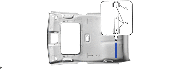
B439358C01
4.74,0.74 5.042,0.958 true 4.844,0.188 5.073,0.344 true 4.719,0.24 5.052,0.958 5.052,0.958 4.74,1.208 true 5.083,0.854 5.396,1.01 0.313,0.156 10 false *a 5.094,0.25 5.406,0.406 0.313,0.156 10 false *b
*a Hot-melt Glue *b Marking


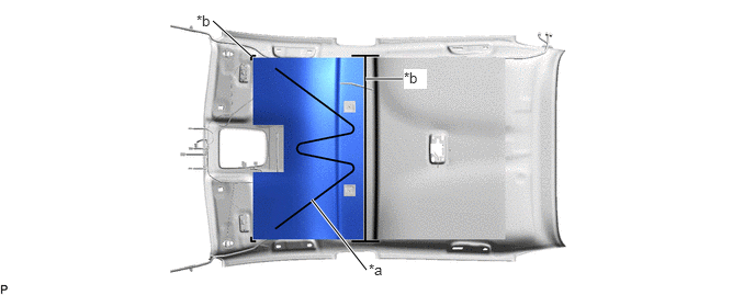
Hide 63351B 2.INSTALL ROOF HEADLINING PAD (w/ Roof Headlining Pad)

a.

Align the roof headlining pad with the markings on the roof headlining assembly and install it using hot-melt glue as shown in the illustration.
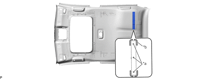
B439359C01
4.708,1.552 5.021,2.281 true 4.844,1.49 5.031,1.635 true 4.719,2.042 5.021,2.271 5.021,2.271 4.719,2.542 true 5.042,2.167 5.354,2.323 0.313,0.156 10 false *a 5.052,1.583 5.365,1.74 0.313,0.156 10 false *b
*a Hot-melt Glue *b Marking


Hide 82171 3.INSTALL NO. 1 ROOF WIRE

a.

Apply butyl tape as shown in the illustration.
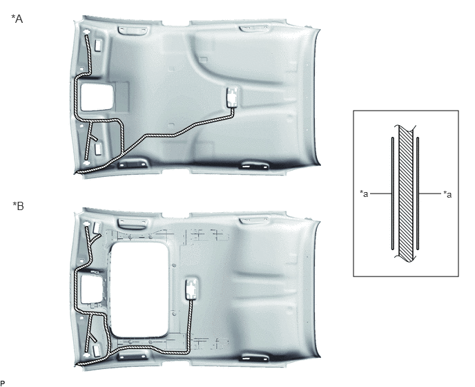
B434613C02
5.333,1.667 6.917,4.167 1.583,2.5 5.583,2.917 5.917,2.917 false 6.323,2.917 6.656,2.917 false 0.188,3 0.583,3.333 0.396,0.333 12 false *B 6.688,2.844 7,3 0.313,0.156 10 false *a 0.167,0.177 0.583,0.5 0.417,0.323 12 false *A 5.427,2.833 5.74,2.99 0.313,0.156 10 false *a
*A w/o Sliding Roof *B w/ Sliding Roof
*a Marking - -
V100155

Butyl Tape - -


NOTICE:

Securely attach the butyl tape.


b.

Turn the 2 visor connectors clockwise approximately 90° to install them to the roof headlining assembly.
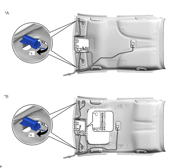
B434631C01
0.188,0.427 0.583,0.833 0.396,0.406 12 false *A 0.167,3.833 0.729,4.333 0.563,0.5 12 false *B 3.802,4.552 4.042,4.781 0.24,0.229 12 true *C 1.188,2.083 1.417,2.25 0.229,0.167 10 true *a 1.167,5.417 1.396,5.583 0.229,0.167 10 true *a
*A w/o Sliding Roof *B w/ Sliding Roof
*C w/ Intrusion Sensor - -
*a 90° - -
V113147

Rotation Direction - -


c.

Engage each clamp.


d.

Align the marking tape (A) on the No. 1 roof wire with the tab on the front side of the roof headlining assembly.
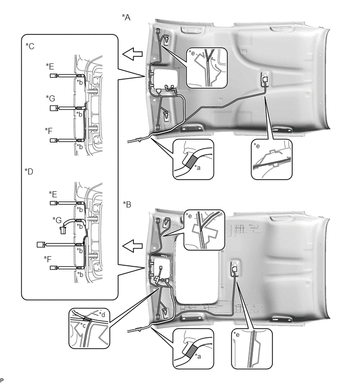
B434616C01
1.865,6.427 2.021,6.479 true 2.5,0.25 2.885,0.563 0.385,0.313 12 false *A 2.521,4.094 2.917,4.417 0.396,0.323 12 false *B 0.521,0.844 0.917,1.167 0.396,0.323 12 false *C 0.5,3.417 0.833,3.74 0.333,0.323 12 false *D 0.938,1.26 1.417,1.667 0.479,0.406 12 false *E 0.917,2.583 1.313,2.906 0.396,0.323 12 false *F 0.938,1.917 1.333,2.333 0.396,0.417 12 false *G 3.99,3.354 4.302,3.51 0.313,0.156 10 false *a 1.573,1.604 1.885,1.76 0.313,0.156 10 false *b 1.646,6.594 1.958,6.75 0.313,0.156 10 false *c 2.031,6.375 2.229,6.573 0.198,0.198 10 true *d 3.875,1 4.021,1.188 0.146,0.188 10 true *e 1,3.885 1.583,4.417 0.583,0.531 12 false *E 0.896,5.219 1.417,5.667 0.521,0.448 12 false *F 1.073,4.417 1.583,4.917 0.51,0.5 12 false *G 4,7.229 4.313,7.385 0.313,0.156 10 false *a 1.563,2.26 1.875,2.417 0.313,0.156 10 false *b 1.573,2.927 1.729,3.094 0.156,0.167 10 true *b 1.573,4.219 1.885,4.375 0.313,0.156 10 false *b 1.573,4.563 1.885,4.719 0.313,0.156 10 false *b 1.573,5.063 1.885,5.219 0.313,0.156 10 false *b 1.583,5.552 1.74,5.74 0.156,0.188 10 true *b 5.208,2.906 5.521,3.063 0.313,0.156 10 false *e 3.813,4.344 3.99,4.521 0.177,0.177 10 true *e 4.792,6.781 4.969,6.958 0.177,0.177 10 true *e
*A w/o Sliding Roof *B w/ Sliding Roof
*C w/o Toyota Safety Sense *D w/ Toyota Safety Sense
*E for LHD with Humidity Sensor or Rain Sensor *F for RHD with Humidity Sensor or Rain Sensor
*G w/ EC Mirror - -
*a Marking Tape (A) *b Marking Tape (B)
*c Marking Tape (C) *d Marking
*e Adjustment Area - -
V100136

Front - -


e.

Align the edge of each marking tape (B) on the No. 1 roof wire with each notch on the roof headlining assembly.


f.

w/ Sliding Roof:

i.

Align the edge of the marking tape (C) on the No. 1 roof wire with the marking on the roof headlining assembly.


g.

Attach the No. 1 roof wire with the butyl tape.

NOTICE:
·

Securely attach the No. 1 roof wire.

·

If any of the No. 1 roof wire is left loose, it will cause an abnormal noise.

·

Make sure to attach the No. 1 roof wire without leaving any of it loose.


HINT:

Secure the extra length of the No. 1 roof wire in the adjustment area.


h.

Install the No. 1 roof wire to the roof headlining assembly with adhesive tape.
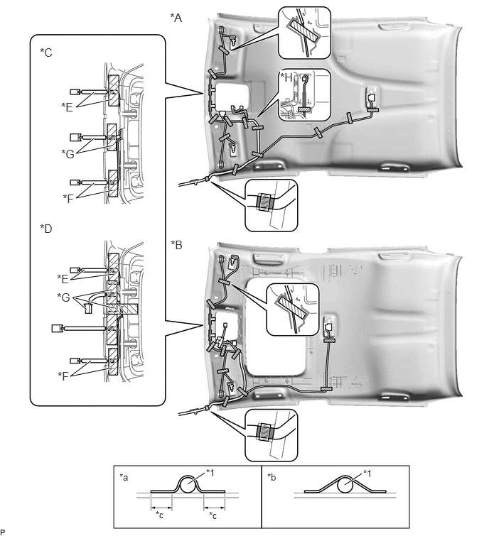
B434634C01
1.667,6.833 3.833,7.75 2.167,0.917 3.833,6.833 6,7.75 2.167,0.917 2.75,7.104 3,6.938 true 5.052,7.115 5.302,6.948 true 1.646,1.458 1.115,1.573 1.115,1.573 1.375,1.354 true 1.073,4.365 1.667,4.521 true 1.646,2.135 1.115,2.25 1.115,2.25 1.375,2.031 true 1.646,5.396 1.031,5.521 1.031,5.521 1.333,5.292 true 1.271,4.542 1.063,4.365 1.063,4.365 1.635,4.25 true 1.667,4.021 1.031,4.104 1.031,4.104 1.24,3.958 true 1.646,2.792 1.115,2.906 1.115,2.906 1.375,2.688 true 2.49,0.156 2.917,0.5 0.427,0.344 12 false *A 2.5,3.49 2.927,3.833 0.427,0.344 12 false *B 0.583,0.667 1,0.917 0.417,0.25 12 false *C 0.583,3.25 0.979,3.615 0.396,0.365 12 false *D 0.896,1.469 1.25,1.781 0.354,0.313 12 false *E 0.917,2.813 1.396,3.313 0.479,0.5 12 false *F 0.896,2.156 1.229,2.49 0.333,0.333 12 false *G 4.104,1.031 4.302,1.208 0.198,0.177 12 true *H 3.021,6.854 3.333,7.01 0.313,0.156 10 false *1 1.75,6.917 2.063,7.073 0.313,0.156 10 false *a 3.917,6.917 4.229,7.073 0.313,0.156 10 false *b 2.281,7.469 2.594,7.625 0.313,0.156 10 false *c 3.063,7.479 3.375,7.635 0.313,0.156 10 false *c 5.323,6.865 5.635,7.021 0.313,0.156 10 false *1 0.833,3.99 1.26,4.396 0.427,0.406 12 false *E 0.844,5.417 1.333,5.813 0.49,0.396 12 false *F 0.833,4.26 1.302,4.604 0.469,0.344 12 false *G
*A w/o Sliding Roof *B w/ Sliding Roof
*C w/o Toyota Safety Sense *D w/ Toyota Safety Sense
*E for LHD with Humidity Sensor or Rain Sensor *F for RHD with Humidity Sensor or Rain Sensor
*G w/ EC Mirror *H w/ Intrusion Sensor
*1 No. 1 Roof Wire - -
*a Correct *b Incorrect
*c 15 mm (0.591 in.) or more - -
V100155

Adhesive Tape - -


NOTICE:
·

Apply the tape securely in place.

·

Do not touch the adhesive surface when applying the tape to prevent adhesion failure.


Hide 89732A 4.INSTALL THEFT WARNING ULTRASONIC SENSOR (w/ Intrusion Sensor)

Hide 81340 5.INSTALL VANITY LIGHT ASSEMBLY

HINT:

Use the same procedure for the RH side and LH side.
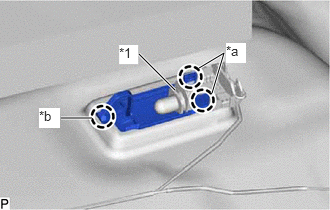

a.
B434625C01
1.823,0.938 1.448,0.563 true 2.208,0.969 2.333,0.552 2.333,0.552 2.073,0.708 true 0.958,1.229 0.635,1.229 true 1.24,0.469 1.438,0.667 0.198,0.198 10 true *1 2.354,0.448 2.563,0.656 0.208,0.208 10 true *a 0.406,1.125 0.625,1.333 0.219,0.208 10 true *b
*1 Bulb Holder
*a Claw (A)
*b Claw (B)


Engage the claw (B) to install the vanity light assembly.


b.

Engage the 2 claws (A) to install the bulb holder to the vanity light assembly.


Hide 86101J 6.INSTALL NO. 2 ANTENNA CORD SUB-ASSEMBLY

Hide 63342 7.INSTALL NO. 2 ROOF SILENCER PAD (w/o Sliding Roof)

a.

Align the No. 2 roof silencer pad with the markings on the roof headlining assembly and install it using hot-melt glue as shown in the illustration.
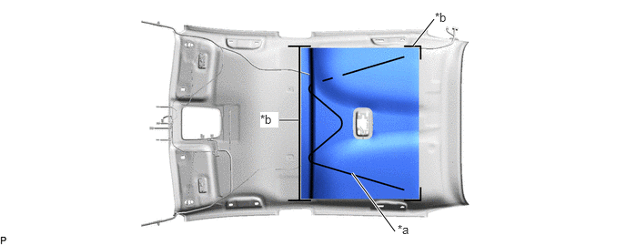
B438434C02
4.729,0.521 4.969,0.219 true 4.521,2.646 4.031,1.979 true 3.417,1.375 3.198,1.375 true 4.552,2.542 4.76,2.75 0.208,0.208 10 true *a 4.979,0.115 5.292,0.271 0.313,0.156 10 false *b 2.979,1.281 3.188,1.458 0.208,0.177 10 true *b
*a Hot-melt Glue *b Marking


Hide 63341 8.INSTALL NO. 1 ROOF SILENCER PAD (w/o Sliding Roof)

a.

Align the No. 1 roof silencer pad with the markings on the roof headlining assembly and install it using hot-melt glue as shown in the illustration.
B438433C02
3.469,0.75 3.823,0.75 true 2.958,1.896 3.479,2.563 true 2.021,0.198 2.385,0.531 true 3.5,2.479 3.719,2.688 0.219,0.208 10 true *a 3.833,0.656 4.052,0.844 0.219,0.188 10 true *b 1.865,0.115 2.177,0.271 0.313,0.156 10 false *b
*a Hot-melt Glue *b Marking