RM3210E
_55
Steering
_047548
STEERING COLUMN
_0242572
STEERING PAD SWITCH
A
STEERING COLUMN STEERING PAD SWITCH REMOVAL
CAUTION / NOTICE / HINT
The necessary procedures (adjustment, calibration, initialization, or registration) that must be performed after parts are removed, installed, or replaced during the steering pad switch assembly removal/installation are shown below.
| Replacement Part or Procedure | Necessary Procedures | Effects / Inoperative when not performed | Link |
|---|---|---|---|
| Disconnect cable from negative auxiliary battery terminal | Memorize steering angle neutral point | Lane departure alert system (w/ Steering Control) | ( ) |
| Intelligent clearance sonar system | |||
| Simple intelligent parking assist system | |||
| Pre-crash safety system | |||
| Parking assist monitor system | ()
|
||
| Initialize back door lock | Power door lock control system | ()
|
PROCEDURE

 45130
1.REMOVE HORN BUTTON ASSEMBLY
84250A
2.REMOVE STEERING PAD SWITCH ASSEMBLY
a.
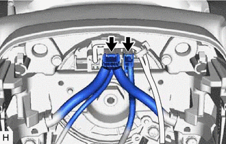
Disconnect 2 connectors from the spiral cable with sensor sub-assembly.
b.
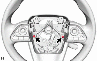
Remove the 2 screws.
c.
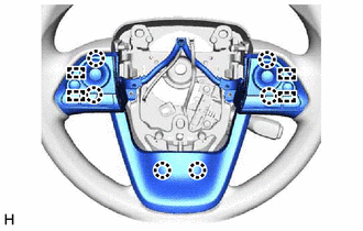
Disengage the 6 claws and 4 pins to remove the steering pad switch assembly.