RM3210E
_59
Vehicle Exterior
_047533
LIGHTING (EXT)
_0244230
AUTOMATIC HIGH BEAM SYSTEM
U
LIGHTING (EXT) AUTOMATIC HIGH BEAM SYSTEM TERMINALS OF ECU
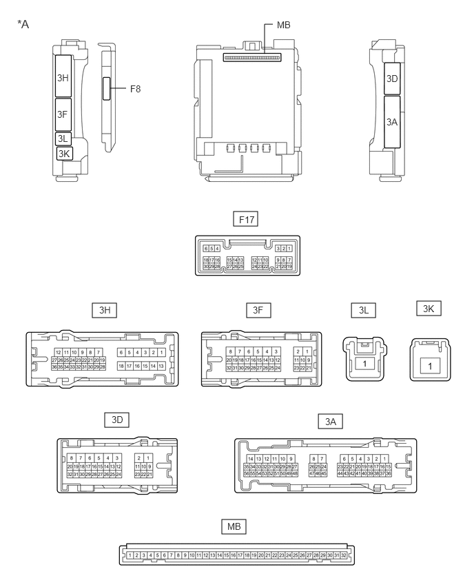
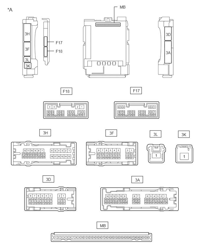
CHECK INSTRUMENT PANEL JUNCTION BLOCK ASSEMBLY AND MAIN BODY ECU (MULTIPLEX NETWORK BODY ECU)
3.531,3.198 3.896,3.417
0.365,0.219
1.396,4.583 1.76,4.802
0.365,0.219
3.729,4.583 4.094,4.802
0.365,0.219
5.313,4.583 5.677,4.802
0.365,0.219
6.302,4.552 6.667,4.771
0.365,0.219
1.583,6.24 1.948,6.458
0.365,0.219
4.813,6.26 5.177,6.479
0.365,0.219
3.354,7.854 3.719,8.073
0.365,0.219
1.667,1.333 1.906,1.333
false
4,0.813 4,0.365
4,0.365 4.125,0.365
false
0.865,1.094 1.177,1.292
0.313,0.198
10
false
3H
0.865,1.646 1.177,1.844
0.313,0.198
10
false
3F
0.875,2.01 1.188,2.208
0.313,0.198
10
false
3L
0.885,2.24 1.198,2.438
0.313,0.198
10
false
3K
1.969,1.26 2.281,1.458
0.313,0.198
10
false
F8
4.188,0.292 4.5,0.49
0.313,0.198
10
false
MB
5.844,1.104 6.156,1.302
0.313,0.198
10
false
3D
5.844,1.76 6.156,1.958
0.313,0.198
10
false
3A
3.615,3.24 3.927,3.438
0.313,0.198
10
false
F17
1.5,4.604 1.813,4.802
0.313,0.198
10
false
3H
3.823,4.604 4.135,4.802
0.313,0.198
10
false
3F
5.427,4.604 5.74,4.802
0.313,0.198
10
false
3L
6.396,4.583 6.708,4.781
0.313,0.198
10
false
3K
1.688,6.26 2,6.458
0.313,0.198
10
false
3D
4.917,6.292 5.229,6.49
0.313,0.198
10
false
3A
3.438,7.875 3.75,8.073
0.313,0.198
10
false
MB
0.26,0.26 0.677,0.531
0.417,0.271
12
false
*A
| *A | Main Body ECU (Multiplex Network Body ECU) with 1 Connector | - | - |
2.146,3.104 2.542,3.344
0.396,0.24
4.604,3.083 5,3.323
0.396,0.24
1.396,4.573 1.792,4.813
0.396,0.24
3.729,4.583 4.125,4.823
0.396,0.24
5.292,4.615 5.688,4.854
0.396,0.24
6.292,4.625 6.688,4.865
0.396,0.24
4.646,6.229 5.042,6.469
0.396,0.24
1.51,6.208 1.906,6.448
0.396,0.24
3.417,7.844 3.813,8.083
0.396,0.24
1.667,1.479 1.906,1.479
false
4.031,0.813 4.031,0.24
4.031,0.24 4.146,0.24
false
1.667,1.802 1.906,1.802
false
1.969,1.427 2.281,1.625
0.313,0.198
10
false
F17
4.229,0.167 4.542,0.365
0.313,0.198
10
false
MB
0.875,1.115 1.188,1.313
0.313,0.198
10
false
3H
0.885,1.656 1.198,1.854
0.313,0.198
10
false
3F
0.885,2.031 1.198,2.229
0.313,0.198
10
false
3L
0.896,2.25 1.208,2.448
0.313,0.198
10
false
3K
1.969,1.729 2.281,1.927
0.313,0.198
10
false
F18
5.854,1.135 6.167,1.333
0.313,0.198
10
false
3D
5.854,1.781 6.167,1.979
0.313,0.198
10
false
3A
4.698,3.125 5.01,3.323
0.313,0.198
10
false
F17
2.219,3.146 2.531,3.344
0.313,0.198
10
false
F18
1.521,4.615 1.833,4.813
0.313,0.198
10
false
3H
3.865,4.625 4.177,4.823
0.313,0.198
10
false
3F
5.417,4.667 5.729,4.865
0.313,0.198
10
false
3L
6.406,4.677 6.719,4.875
0.313,0.198
10
false
3K
1.625,6.26 1.938,6.458
0.313,0.198
10
false
3D
4.771,6.281 5.083,6.479
0.313,0.198
10
false
3A
3.531,7.896 3.844,8.094
0.313,0.198
10
false
MB
0.26,0.24 0.677,0.49
0.417,0.25
12
false
*A
| *A | Main Body ECU (Multiplex Network Body ECU) with 2 Connectors | - | - |
a.
Measure the voltage and check for pulses according to the value(s) in the table below.
| Terminal No. (Symbol) | Wiring Color | Terminal Description | Condition | Specified Condition |
|---|---|---|---|---|
| 3F-31 - Body ground | G - Body ground | H-LP LH relay drive output | Power switch off | 11 to 14 V |
| Power switch on (IG) | Below 1 V | |||
| F17-1 (DIM) - Body ground | BE - Body ground | H-LP RH relay drive output | Power switch off | 11 to 14 V |
| Power switch on (IG) | Below 1 V | |||
| F17-8 (A) - Body ground | W - Body ground | Light control switch AUTO position signal input | Light control switch in AUTO position | Below 1 V |
| Light control switch not in AUTO position | Pulse generation | |||
| F17-12 (HEAD) - Body ground | G - Body ground | Light control switch head position input | Light control switch in head position | Below 1 V |
| Light control switch not in head position | Pulse generation | |||
| F17-20 (CLTS) - Body ground | R - Body ground | Automatic light control sensor signal input | Power switch off | Below 1 V |
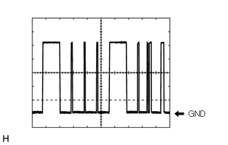
| Automatic light control system operating | Communication waveform generation
(See waveform 1) |
|||
| F17-19 (CLTB) - F17-21 (CLTE) | BR - G | Automatic light control sensor power supply output | Power switch off | Below 1 V |
| Power switch on (IG) | 11 to 14 V | |||
| F17-24 (HU) - Body ground | P - Body ground | Dimmer switch high position signal input | Dimmer switch in high position | Below 1 V |
| Dimmer switch not in high position | Pulse generation | |||
| F17-17 (AHBI) - Body ground | B - Body ground | Auto matic high beam main switch signal input | Power switch on (IG), auto matic high beam main switch on | Below 1 V |
| Power switch on (IG), auto matic high beam main switch off | 11 to 14 V |
If the result is not as specified, the main body ECU (multiplex network body ECU) or instrument panel junction block assembly may be malfunctioning.
i.
2.844,1.646 3.219,1.813
0.375,0.167
10
false
GND
Waveform 1
| Item | Content |
|---|---|
| Tool setting | 2 V/DIV., 10 ms./DIV. |
- HINT:
-
The communication waveform changes according to the surrounding brightness.
CHECK FORWARD RECOGNITION CAMERA
Click hereEngine / Hybrid System>CRUISE CONTROL>FORWARD RECOGNITION CAMERA SYSTEM>TERMINALS OF ECU