SYSTEM DESCRIPTION
Troubleshooting · Vehicles built from Nov 2005
| RADIO AND NAVIGATION ASSEMBLY OUTLINE |
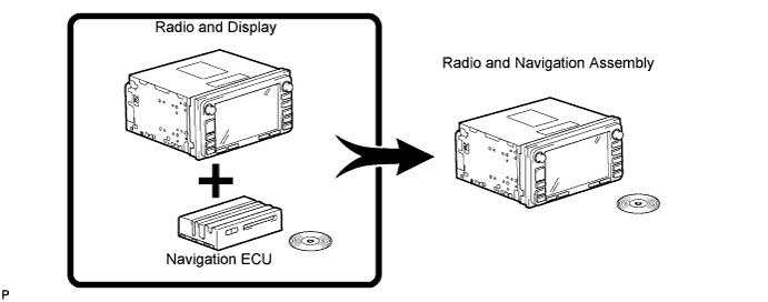
Conventionally, 2 separate devices, a "radio and display" and a "navigation ECU", are used. In this model, these 2 devices are combined into a single unit.

| NAVIGATION SYSTEM OUTLINE |
Vehicle position tracking methods
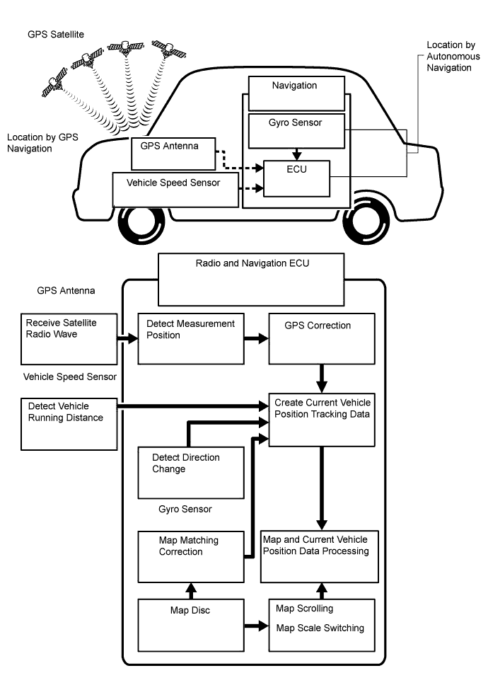
It is essential that the navigation system correctly tracks the current vehicle position and displays it on the map. There are 2 methods to track the current vehicle position: autonomous (dead reckoning) and GPS* (satellite) navigation. Both navigation methods are used in conjunction with each other.
- HINT:
- *: GPS (Global Positioning System)
Operation
Description
Vehicle Position Calculation
Radio and navigation assembly calculates current vehicle position (direction and current position) using direction deviation signal from gyro sensor and running distance signal from vehicle speed sensor, and creates driving route.
Map Display processing
Radio and navigation assembly displays vehicle track map by processing vehicle position data, vehicle running track, and map data from map disc.
Map Matching
Map data from the map disc is compared to vehicle position and running track data. Then, vehicle position is matched with nearest road.
GPS Correction
Vehicle position is matched to position measured by GPS. Then, measurement position data from GPS unit is compared with vehicle position and running track data. If the position is very different, GPS measurement position is used.
Distance Correction
Running distance signal from vehicle speed sensor includes error caused by tire wear and slippage between tires and road surface. Distance correction is performed to account for this. Radio and navigation assembly automatically offsets the running distance signal to make up for difference between it and distance data of map. Offset is automatically updated.
- HINT:
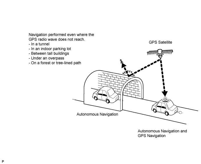
- The combination of autonomous and GPS navigation makes it possible to display the vehicle position even when the vehicle is in places where the GPS radio wave cannot receive a signal. When only autonomous navigation is used, however, the mapping accuracy may slightly decline.
Autonomous navigation
This method determines the relative vehicle position based on the running track determined by the gyro and vehicle speed sensors located in the radio and navigation assembly.Gyro sensor
Calculates the direction by detecting angular velocity. It is located in the radio and navigation assembly.Vehicle speed sensor
Used to calculated the vehicle running distance.
GPS navigation (Satellite navigation)
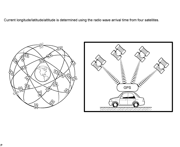
This method detects the absolute vehicle position using radio wave from a GPS satellite*.- HINT:
- *: GPS satellites were launched by the U.S. Department of Defense for military purposes.
Number of satellites
Measurement
Description
2 or less
Measurement impossible
Vehicle position cannot be obtained because number of satellites is not enough.
3
2-dimensional measurement is possible
Vehicle position is obtained based on current longitude and latitude (this is less precise than 3-dimensional measurement).
4
3-dimensional measurement is possible
Vehicle position is obtained based on current longitude, latitude and altitude.
Map matching
The current driving route is calculated by autonomous navigation (according to the gyro sensor and vehicle speed sensor) and GPS navigation. This information is then compared with possible road shapes from the map data in the map disc and the vehicle position is set onto the most appropriate road.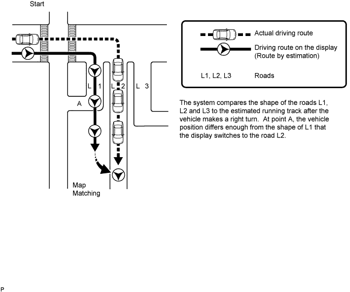
| MULTI-DISPLAY OUTLINE |
Touch switch
Touch switches are touch-sensitive (interactive) switches operated by touching the screen. When a switch is pressed, the outer glass bends in to contact the inner glass at the pressed position. By doing this, the voltage ratio is measured and the pressed position is detected.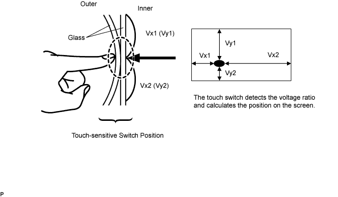
| DVD (DIGITAL VERSATILE DISC) PLAYER OUTLINE (For Navigation Map) |
The radio and navigation assembly uses a laser pickup to read the digital signals recorded on a DVD.
- CAUTION:
- Because the navigation system uses an invisible laser beam, do not look directly at the laser pickup. Be sure to only operate the navigation as instructed.
- NOTICE:
- Do not disassemble any part of the radio and navigation assembly.
- Do not apply oil to the radio and navigation assembly.
- Do not insert anything but a DVD into the radio and navigation assembly.
- Do not disassemble any part of the radio and navigation assembly.
| CD (COMPACT DISC) PLAYER OUTLINE |
A compact disc player uses a laser pickup to read digital signals recorded on a compact disc (CD). By converting the digital signals to analog, it can play music and other audio.
- NOTICE:
- Do not disassemble any part of the CD player.
- Do not apply oil to CD player.
- Do not insert anything but a CD into the CD player.
- Do not disassemble any part of the CD player.
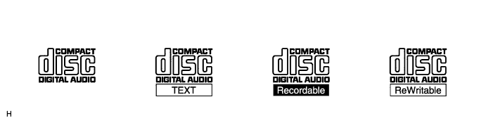
USABLE DISC
This player is compatible only with music CDs, CD-Rs (CD-Recordable) and CD-RWs (CD-ReWritable) with the marks shown in the illustration below.
PRECAUTIONS FOR HANDLING DISC
- NOTICE:
- Copy-controlled CDs cannot be used.
- Some CD-Rs and CD-RWs are not playable as a result of: 1) the type of recording method used, 2) the type of disc, 3) scratches, 4) contamination, or 5) the disc being in the vehicle for an extended amount of time, leading to deterioration.
- CD-Rs and CD-RWs that have not been finalized cannot be played.
- When handling a disc, be careful not to put fingerprints, stains or scratches on the disc.
- When holding a disc, pinch the center hole and edge of the disc with your fingers. Face the printed side upward.
- If a disc is ejected by pressing the eject button and left partially ejected for an extended period of time, the disc may become deformed and unusable.
- A disc may not be able to be ejected or the player may become damaged if: 1) cellophane tape, stickers, CD-R labels or rental CD labels are attached; or 2) residue from removed tape, stickers or labels remain.
- Avoid direct sunlight when storing discs as they may become deformed and unusable.
- Do not use uniquely-shaped discs as they may damage the player.
- Do not use discs where part of the recording surface is transparent or translucent. If used, the disc may become unable to be inserted, ejected and played normally.
- Copy-controlled CDs cannot be used.
- HINT:
- Just as condensation fogs the vehicle's windows during wet or cold weather, condensation may also form inside the player. If condensation forms, CD skipping or playback stoppage may occur. Ventilate or dehumidify the vehicle for a while before using the player.
- If the player vibrates severely due to driving on a rough road, the CD may skip.
- Just as condensation fogs the vehicle's windows during wet or cold weather, condensation may also form inside the player. If condensation forms, CD skipping or playback stoppage may occur. Ventilate or dehumidify the vehicle for a while before using the player.
| MP3 / WMA OUTLINE |
COMPATIBLE MP3 FILE FORMAT
Compatible format
MP3 (MPEG1 LAYER3, MPEG2 LSF LAYER3)
Compatible sampling frequency
- MPEG1 LAYER3: 32, 44.1, 48 (kHz)
- MPEG2 LSF LAYER3: 16, 22.05, 24 (kHz)
Compatible bit rate
- MPEG1 LAYER3: 64, 80, 96, 112, 128, 160, 192, 224, 256, 320 (kbps)
- MPEG2 LSF LAYER3: 64 80, 96, 112, 128, 144, 160 (kbps)
- Compatible with VBR
Compatible channel mode
Stereo, joint stereo, dual channel and monaural
- MPEG1 LAYER3: 32, 44.1, 48 (kHz)
COMPATIBLE WMA FILE FORMAT
Compatible format
WMA Ver. 7, 8, 9
Compatible sampling frequency
32, 44.1, 48 (kHz)
Compatible bit rate
- Ver. 7, 8: CBR48, 64, 80, 96, 128, 160, 192 (kbps)
- Ver. 9: CBR48, 64, 80, 96, 128, 160, 192, 256, 320 (kbps)
- Compatible only with 2 ch playback
- Ver. 7, 8: CBR48, 64, 80, 96, 128, 160, 192 (kbps)
ID3 TAG / WMA TAG INFORMATION
MP3 files have ID3 tags, in which supplemental text information can be input. Song titles and artist names can be saved.
- HINT:
- This player is compatible with ver. 1.0 (1.1), and ver. 2.2 (2.3) ID3 tags. The text limit complies with ver. 1.0 (1.1).
WMA files have WMA tags, in which supplemental text information can be input. Song titles and artist names can be saved.
COMPATIBLE MEDIA INFORMATION
Only media such as CD-ROMs, CD-Rs (CD-Recordable) and CD-RWs (CD-ReWritable) are useable for MP3 / WMA playback.
- NOTICE:
- CD-Rs and CD-RWs are more vulnerable to high temperature and humidity than normal audio CDs. As a result, some CD-Rs and CD-RWs may not be playable.
- If a disc has fingerprints or becomes scratched, the disc may not be playable or the CD may skip.
- Some CD-Rs and CD-RWs may deteriorate if left in the vehicle for a long time.
- Store CD-Rs and CD-RWs in a non-transparent case, as the discs are vulnerable to ultraviolet rays.
- CD-Rs and CD-RWs are more vulnerable to high temperature and humidity than normal audio CDs. As a result, some CD-Rs and CD-RWs may not be playable.
COMPATIBLE MEDIA FORMAT INFORMATION
COMPATIBLE MEDIA FORMAT
Disc format
CD-ROM Mode1, CD-ROM XA Mode2 Form1
File format
ISO9660 level1, level2
| BLUETOOTH OUTLINE |
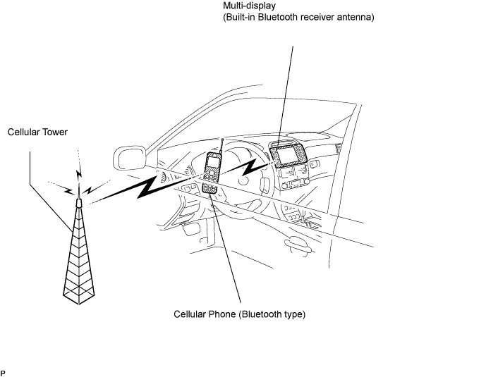
Bluetooth is a new wireless connection technology that uses the 2.4 GHz frequency band. This makes it possible to connect a cellular phone (Bluetooth capable phone*) to the multi-display (Bluetooth system is built-in), and use a handsfree function with the cellular phone in a pocket or bag. As a result, it is not necessary to use a connector for the cellular phone.
- HINT:
- The communication performance of Bluetooth may vary depending on obstructions or radio wave conditions between communication devices, electromagnetic radiation, communication device sensitivity, or antenna capacity.
| DIAGNOSTIC FUNCTION OUTLINE |
- HINT:
- Illustrations may differ from the actual vehicle depending on the device settings and options. Therefore, some detailed areas may not be exactly the same as on the actual vehicle.
- After the ignition switch is turned on (IG or ACC), check that the map is displayed before starting the diagnostic mode. Otherwise, some items cannot be checked.
- Illustrations may differ from the actual vehicle depending on the device settings and options. Therefore, some detailed areas may not be exactly the same as on the actual vehicle.
Start diagnostic mode
There are 2 methods to start diagnostic mode. Start the mode by using one of them.
Method 1
- Start the engine.
- While pressing and holding the "INFO" switch, operate the light control switch: OFF → Turn ON → Turn OFF → Turn ON → Turn OFF → Turn ON → Turn OFF.
- The diagnostic mode starts and the "System Check Mode" screen will be displayed. Service inspection starts automatically and the result will be displayed.
- Start the engine.
Method 2
- Start the engine.
-
Press the "DISPLAY" switch.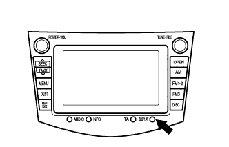
-
From the display quality adjustment screen, touch the corners of the screen in the following order: upper left → lower left → upper left → lower left → upper left → lower left.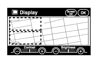
- The diagnostic mode starts and the "System Check Mode" screen will be displayed. Service inspection starts automatically and the result will be displayed.
- Start the engine.
Finish diagnostic mode
There are 2 methods to end diagnostic mode. Use one of them.
- Turn the ignition switch off.
- Press and hold the "DISPLAY" switch for 3 seconds.
- Turn the ignition switch off.