REMOVAL
Removal / installation · Vehicles built Nov 2005 – Dec 2006
Versions by build date: Nov 2005 – Dec 2006 Jan 2007 – Jul 2007 from Aug 2007
| 1.
POSITION FRONT WHEELS FACING STRAIGHT AHEAD |
|
| 2.
DISCONNECT CABLE FROM NEGATIVE BATTERY TERMINAL |
 |
- CAUTION:
- Wait at least 90 seconds after disconnecting the cable from the negative (-) battery terminal to prevent airbag and seat belt pretensioner activation.
| 4.
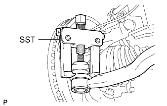
DISCONNECT TIE ROD END SUB-ASSEMBLY LH |
|
Remove the cotter pin and castle nut.
- Using SST, disconnect the tie rod end from the steering knuckle.
- NOTICE:
- Do not damage the tie rod end dust cover.
- SST
- 09628-62011
| 5.
DISCONNECT TIE ROD END SUB-ASSEMBLY RH |
|
- HINT:
- Use the same procedure for the RH side as for the LH side.
| 6.
REMOVE COLUMN HOLE COVER SILENCER SHEET |
|
- Remove the floor carpet, 2 clips and column hole cover silencer.
| 7.
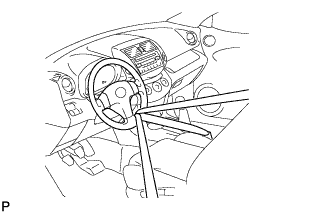
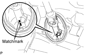
DISCONNECT STEERING SLIDING YOKE SUB-ASSEMBLY |
|
- Use a seat belt to fix the steering wheel in place to avoid breakage of the spiral cable.
- Place matchmarks on the sliding yoke of the steering intermediate shaft.
Remove the bolt and disconnect the sliding yoke.
| 8.
DISCONNECT NO. 1 STEERING COLUMN HOLE COVER SUB-ASSEMBLY |
|
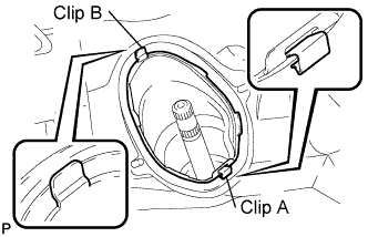
- Remove clip A, detach clip B from the body and disconnect the No. 1 steering column hole cover.
- NOTICE:
- Do not damage clips A and B.
| 9.
REMOVE ENGINE ASSEMBLY WITH TRANSAXLE |
|
for 1AZ-FE:
Remove the engine with transaxle (Click here).
for 2AZ-FE:
Remove the engine with transaxle (Click here).
for 2AD-FHV:
Remove the engine with transaxle (Click here).
for 2AD-FTV:
Remove the engine with transaxle (Click here).
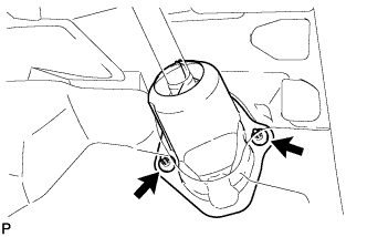
| 10.
REMOVE NO. 1 STEERING COLUMN HOLE COVER SUB-ASSEMBLY |
|
Remove the clamp and disconnect the column hole cover from the steering gear.
| 11.
REMOVE INTERMEDIATE SHAFT |
|
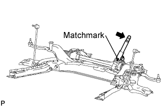
Place matchmarks on the intermediate shaft of the steering gear.
Remove the bolt and disconnect the steering intermediate shaft from the steering gear.
| 12.
REMOVE STEERING GEAR ASSEMBLY |
|
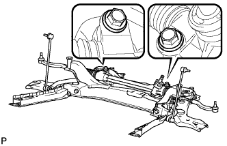
Remove the 2 bolts, 2 nuts and steering gear from the suspension crossmember.
- NOTICE:
- Keep the nut from rotating while turning the bolt.
| 13.
SECURE STEERING GEAR ASSEMBLY |
|
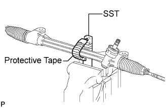
- Using SST wrapped with protective tape, secure the steering gear in a vise.
- SST
- 09612-00012
- HINT:
- Remove and reinstall SST as needed.
| 14.
REMOVE TIE ROD END SUB-ASSEMBLY LH |
|
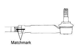
- Put matchmarks on the No. 2 tie rod end subassembly and rack end.
Remove the No. 2 tie rod end sub-assembly and lock nut.
| 15.
REMOVE TIE ROD END SUB-ASSEMBLY RH |
|
- HINT:
- Use the same procedure described for the No. 2 tie rod end sub-assembly.