C0210/33 Right Rear Wheel Speed Sensor Signal
Diagnostic trouble codes · Vehicles built Aug 2007 – Jul 2008
Also covers:
- C0215/34 Left Rear Wheel Speed Sensor Signal
- C1238/38 Foreign Object is Attached on Tip of Rear Speed Sensor RH
- C1239/39 Foreign Object is Attached on Tip of Rear Speed Sensor LH
- C1273/73 Low Output Signal of Rear Speed Sensor RH (Test Mode DTC)
- C1274/74 Low Output Signal of Rear Speed Sensor LH (Test Mode DTC)
- C1277/77 Abnormal Change in Output Signal of Rear Speed Sensor RH (Test Mode DTC)
- C1278/78 Abnormal Change in Output Signal of Rear Speed Sensor LH (Test Mode DTC)
Versions by build date: Nov 2005 – Dec 2006 Jan 2007 – Jul 2007 Aug 2007 – Jul 2008
DESCRIPTION
Refer to DTC C0200/31 (Click here).DTCs C1273/73, C1274/74, C1277/77 and C1278/78 can be deleted when the speed sensor sends a vehicle speed signal or the test mode ends. DTCs C1273/73, C1274/74, C1277/77 and C1278/78 are output only in the test mode.
| DTC No. |
DTC Detection Condition |
Trouble Area |
| C0210/33 C0215/34 |
When one of following conditions is met:
|
|
| C1238/38 C1239/39 |
When either condition below is met:
|
|
| C1273/73 C1274/74 |
Detected only during test mode. |
|
| C1277/77 C1278/78 |
Detected only during test mode. |
|
- HINT:
- DTC C0210/33 and C1238/38 relate to the skid control sensor RH.
- DTC C0215/34 and C1239/39 relate to the skid control sensor LH.
- DTC C0210/33 and C1238/38 relate to the skid control sensor RH.
WIRING DIAGRAM
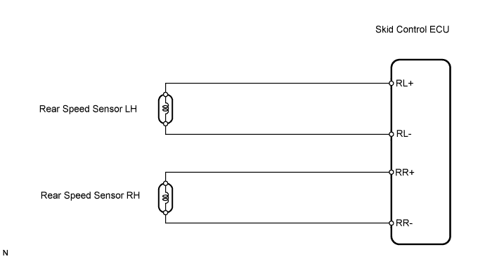

INSPECTION PROCEDURE
- NOTICE:
- Check the speed sensor signal in test mode after cleaning or replacement (Click here).
| 1. CHECK HARNESS AND CONNECTOR (MOMENTARY INTERRUPTION) |

Using the Data List of the intelligent tester, check for any momentary interruption in the wire harness corresponding to a DTC (Click here).
Skid control ECU Item (Display)
Measurement Item / Range (Display)
Normal Condition
Diagnostic Note
RR Speed Open
RR speed sensor open detection / ERROR or NORMAL
ERROR: Momentary interruption
NORMAL: Normal
-
RL Speed Open
RL speed sensor open detection / ERROR or NORMAL
ERROR: Momentary interruption
NORMAL: Normal
-
- OK:
- There are no momentary interruptions.
- HINT:
- Perform this inspection before removing the sensor and connector.
|
|
||||

| OK | |
 |
| 2. READ VALUE USING INTELLIGENT TESTER (REAR SPEED SENSOR) |
Check the Data List for proper functioning of the rear speed sensor.
Skid control ECU Item (Display)
Measurement Item / Range (Display)
Normal Condition
Diagnostic Note
RR Wheel Speed
Wheel speed sensor (RR) reading / min.: 0 km/h (0 mph), max.: 326 km/h (202.8 mph)
Similar to speed indicated on speedometer
-
RL Wheel Speed
Wheel speed sensor (RL) reading / min.: 0 km/h (0 mph), max.: 326 km/h (202.8 mph)
Similar to speed indicated on speedometer
-
- OK:
- There is almost no difference between actual wheel speed and displayed speed value.
- HINT:
- There is a tolerance of +-10% in the speedometer indication.
|
|
||||

| OK | |
|
| 3. PERFORM TEST MODE INSPECTION (SIGNAL CHECK) |
Perform a TEST MODE inspection and check for DTCs (Click here).
- OK:
- No DTCs output.
|
|
||||
| OK | |
|
| 4. RECONFIRM DTC |
Clear the DTC(s) (Click here).
Start the engine.
Drive the vehicle at a speed of 20 km/h (12 mph) or more for at least 60 seconds.
Check if the same DTC(s) is output (Click here).
Result Result
Proceed to
DTC is not output
A
DTC is output
B
|
|
||||
| A | ||
 |
||
| ||
| 5. INSPECT REAR SPEED SENSOR (INSTALLATION) |
Check the speed sensor installation.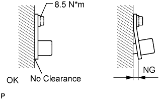
- OK:
- The installation bolt is tightened properly and there is no clearance between the sensor and rear axle carrier.
- Torque:
- 8.5 N*m{ 87 kgf*cm , 75 in.*lbf }
- HINT:
- Check the speed sensor signal after the replacement (Click here).
|
|
||||
| OK | |
|
| 6. CHECK REAR SPEED SENSOR (TIP) |
Remove the rear speed sensor.
Check the sensor tip.
- OK:
- No scratches or foreign matter on the sensor tip.
|
|
||||
| OK | |
|
| 7. CHECK WIRE HARNESS (SKID CONTROL ECU - REAR SPEED SENSOR) |
Disconnect the A26 ECU connector.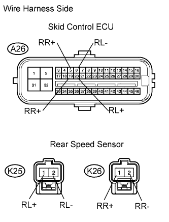
Disconnect K25 and K26 sensor connectors.
Measure the resistance of the wire harness side connectors.
- Standard resistance:
- for LH Side:
Tester Connection
Specified Condition
A26-20 (RL+) - K25-1 (RL+)
Below 1 Ω
A26-6 (RL-) - K25-2 (RL-)
Below 1 Ω
A26-20 (RL+) - Body ground
10 kΩ or higher
A26-6 (RL-) - Body ground
10 kΩ or higher
- for RH Side:
Tester Connection
Specified Condition
A26-5 (RR+) - K26-1 (RR+)
Below 1 Ω
A26-19 (RR-) - K26-2 (RR-)
Below 1 Ω
A26-5 (RR+) - Body ground
10 kΩ or higher
A26-19 (RR-) - Body ground
10 kΩ or higher
|
|
||||
| OK | |
|
| 8. CHECK SKID CONTROL ECU (SENSOR INPUT VOLTAGE) |
Disconnect K25 and K26 sensor connectors.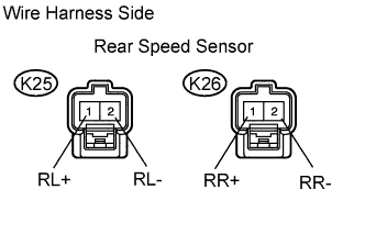
Measure the voltage of the wire harness side connectors.
- Standard voltage:
Tester Connection
Condition
Specified Condition
K25-1 (RL+) - Body ground
Ignition switch on (IG)
5.7 to 17.3 V
K26-1 (RR+) - Body ground
Ignition switch on (IG)
5.7 to 17.3 V
|
|
||||
| OK | |
|
| 9. RECONFIRM DTC |
Clear the DTC(s) (Click here).
Start the engine.
Drive the vehicle at a speed of 20 km/h (12 mph) or more for at least 60 seconds.
Check if the same DTC(s) is output (Click here).
Result Result
Proceed to
DTC is output
A
DTC is not output
B
|
|
||||
| A | |
|
| 10. REPLACE REAR SPEED SENSOR |
Replace the rear speed sensor.
| NEXT | |
|
| 11. RECONFIRM DTC |
Clear the DTC(s) (Click here).
Start the engine.
Drive the vehicle at a speed of 20 km/h (12 mph) or more for at least 60 seconds.
Check if the same DTC(s) is output (Click here).
Result Result
Proceed to
DTC is output
A
DTC is not output
B
|
|
||||
| A | ||
|
||
| ||