INSTALLATION
Removal / installation · Vehicles built from Aug 2008
Versions by build date: Nov 2005 – Jul 2008 from Aug 2008
| 1.
INSTALL FUEL TANK ASSEMBLY |
 |
Set the fuel tank on a transmission jack.
Lift up the transmission jack.
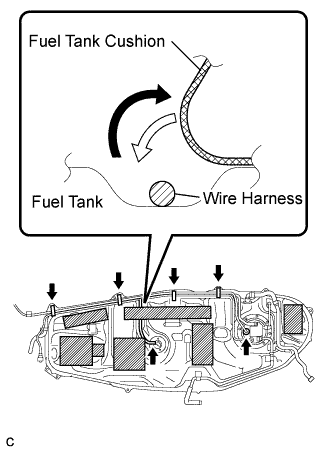
Fold back approximately half of any cushion rubber necessary for the attachment of the wire harness to the fuel tank.
Connect the fuel pump connector and sender gauge connector to the fuel tank.
- NOTICE:
- Be careful not to cut the wiring.
Attach the wire harness to the 4 clamps.
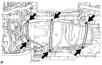
- Install the 3 fuel tank bands with the 6 bolts.
-
Torque:
- 40 N*m{
408 kgf*cm
, 30 ft.*lbf
}
| 2.
INSTALL FUEL TANK FILLER PIPE |
|
Install the filler pipe with the 2 bolts.
-
Torque:
- 24 N*m{
240 kgf*cm
, 17 ft.*lbf
}
Install the filler pipe protector with the 3 bolts.
-
Torque:
- 5.4 N*m{
55 kgf*cm
, 48 in.*lbf
}
| 3.
CONNECT FUEL TANK TO FILLER PIPE HOSE |
|
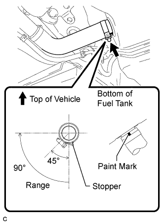
Connect the filler pipe hose to the fuel tank as shown in the illustration.
- HINT:
- Position the fuel tank to filler pipe hose so that the protrusion faces towards the bottom of the fuel tank when connecting the hose.
- Tighten the hose clamp until the end of the hose clamp contacts the stopper as shown in the illustration.
| 4.
INSTALL FUEL HOSE PROTECTOR |
|
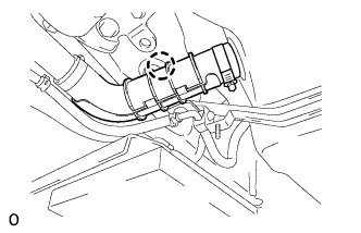
- Attach the claw to install the fuel hose protector to the filler pipe hose.
| 5.
CONNECT FUEL TANK BREATHER HOSE |
|
- Connect the fuel tank breather hose to the fuel tank.
- NOTICE:
- Before installing the hose, make sure that the hose and pipe are not damaged. Make sure that there is no dirt present on the connecting surfaces.
- After connecting the hose and pipe, check that they are securely connected by trying to pull them apart.
| 6.
CONNECT AIR INLET LINE HOSE |
|
- Connect the air inlet line hose.
| 7.
CONNECT FUEL TANK MAIN TUBE SUB-ASSEMBLY |
|
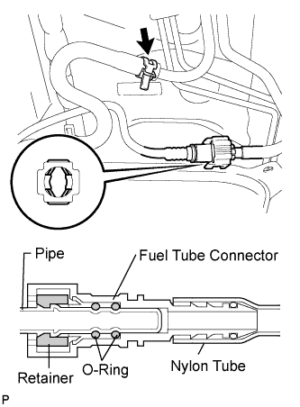
- NOTICE:
- Before installing the tube connector to the pipe, check the connector for damage and foreign matter.
- Connect the main tube connector to the pipe. Push the 2 parts together firmly until a "click" sound is heard.
- NOTICE:
- Check that the connector and pipe are securely connected by trying to pull them apart.
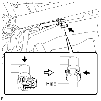
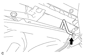
Connect the purge line hose to the pipe.
| 8.
INSTALL NO. 1 FUEL TANK PROTECTOR |
|
Install the fuel tank protector with the 2 bolts.
-
Torque:
- 20 N*m{
204 kgf*cm
, 15 ft.*lbf
}
Install the 2 clips and grommet.
| 9.
INSTALL NO. 2 PARKING BRAKE CABLE ASSEMBLY |
|
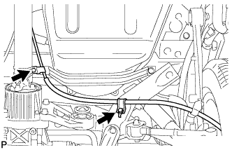
- Install the parking brake cable with the 2 bolts.
-
Torque:
- 6.0 N*m{
61 kgf*cm
, 53 in.*lbf
}
| 10.
INSTALL FUEL TANK CAP |
|
| 11.
CONNECT CABLE TO NEGATIVE BATTERY TERMINAL |
|
| 12.
CHECK FOR FUEL LEAKS
|
|
- Make sure that there are no fuel leaks after performing maintenance on the fuel system.
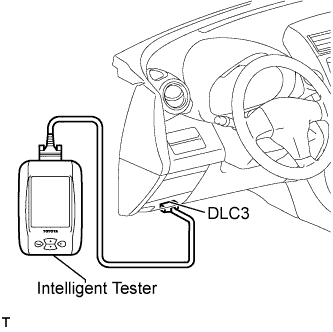
Connect the intelligent tester to the DLC3.
Turn the ignition switch on (IG), and push the intelligent tester main switch ON.
- NOTICE:
- Do not start the engine.
Select the Active Test mode on the intelligent tester.
- HINT:
- Refer to the intelligent tester operator's manual for further details.
Check that there are no leaks from the fuel system.
Turn the ignition switch off.
Disconnect the intelligent tester from the DLC3.