2005-2008 RAV4 · Service Manual BRAKE

TS and CG Terminal Circuit

Circuit diagnosis · Vehicles built from Aug 2008

Versions by build date: Nov 2005 – Jul 2008 from Aug 2008

DESCRIPTION

If the vehicle is stationary during sensor check mode, speed sensor malfunctions cannot be detected. The vehicle must be driven for speed sensor malfunctions to be detected.

HINT:
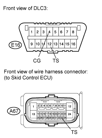
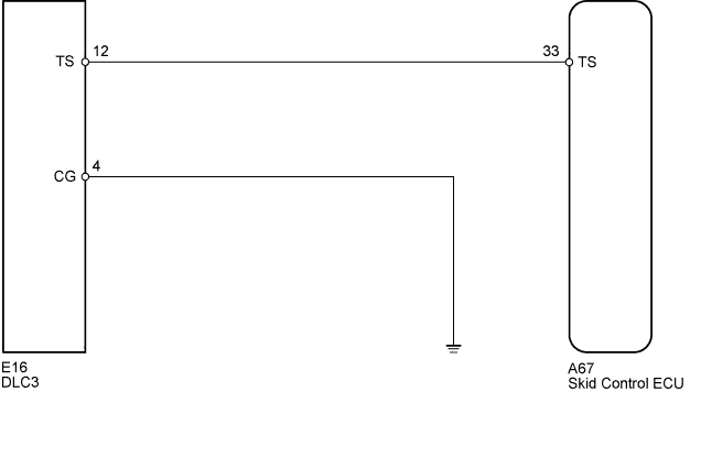
Change to sensor check mode by connecting terminals 12 (TS) and 4 (CG) of the DLC3, and turning the ignition switch from off to ON.


WIRING DIAGRAM

C194154E02

INSPECTION PROCEDURE

NOTICE:
When replacing the brake actuator assembly, perform zero point calibration (Click here).


1. CHECK HARNESS AND CONNECTOR (DLC3 - SKID CONTROL ECU/BODY GROUND)

  1. C194164E02
    Disconnect the skid control ECU connector.

  1. Measure the resistance according to the value(s) in the table below.
    Standard Resistance:
    Tester Connection
    Condition
    Specified Condition
    E16-4 (CG) - Body ground
    Always
    Below 1 Ω
    E16-12 (TS) - A67-33 (TS)
    Always
    Below 1 Ω
    A67-33 (TS) - Body ground
    Always
    10 kΩ or higher


NG
REPAIR OR REPLACE HARNESS OR CONNECTOR
OK

REPLACE BRAKE ACTUATOR ASSEMBLY (Click here)


← TS and CG Terminal Circuit (Nov 2005 – Jul 2008)COMPONENTS (from Nov 2005) →