TERMINALS OF ECU
System information · Vehicles built from Nov 2005
| CHECK COMBINATION METER ASSEMBLY |


Measure the voltage and resistance of the connector.
for LHD Symbols (Terminal No.)
Wiring Color
Terminal Description
Condition
Specified Condition
IG+ (E19-21) - Body ground
B - Body ground
Ignition switch signal
Ignition switch off
Below 1 V
Ignition switch on (ACC)
10 to 14 V
B (E19-22) - Body ground
R - Body ground
Battery
Always
10 to 14 V
CANH (E19-32) - Body ground
G - Body ground
CAN communication line
Ignition switch on (ACC)
Pulse generation
CANL (E19-31) - Body ground
W - Body ground
CAN communication line
Ignition switch on (ACC)
Pulse generation
ET (E19-33) - Body ground
BR - Body ground
Ground
Always
Below 1 Ω
for RHD Symbols (Terminal No.)
Wiring Color
Terminal Description
Condition
Specified Condition
IG+ (E22-21) - Body ground
B - Body ground
Ignition switch signal
Ignition switch off
Below 1 V
Ignition switch on (ACC)
10 to 14 V
B (E22-22) - Body ground
R - Body ground
Battery
Always
10 to 14 V
CANH (E22-32) - Body ground
G - Body ground
CAN communication line
Ignition switch on (ACC)
Pulse generation
CANL (E22-31) - Body ground
W - Body ground
CAN communication line
Ignition switch on (ACC)
Pulse generation
ET (E22-33) - Body ground
BR - Body ground
Ground
Always
Below 1 Ω
| CHECK INSTRUMENT PANEL JUNCTION BLOCK (MAIN BODY ECU) |
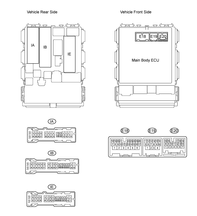
Measure the voltage and resistance of the connectors.
Symbols (Terminal No.)
Wiring Color
Terminal Description
Condition
Specified Condition
KSW (IE-26) - Body ground
L - Body ground
Key unlock warning switch input
Key inserted
Below 1 V
Key removed from ignition key cylinder
10 to 14 V
GND (IE-17) - Body ground
W-B - Body ground
Ground
Always
Below 1 Ω
B (IB-30) - Body ground
R - Body ground
Battery
Always
10 to 14 V
DTCY (IA-21) - Body ground
W - Body ground
Driver door courtesy switch input
Driver door closed
10 to 14 V
Driver door open
Below 1 V
CANL (E20-16) - Body ground
W - Body ground
CAN communication line
Ignition switch on (ACC)
Pulse generation
CANH (E20-15) - Body ground
R - Body ground
CAN communication line
Ignition switch on (ACC)
Pulse generation