REMOVAL
Removal / installation · Vehicles built from Nov 2005
| 1.
DISCONNECT CABLE FROM NEGATIVE BATTERY TERMINAL |
 |
- CAUTION:
- Wait at least 90 seconds after disconnecting the cable from the negative (-) battery terminal to prevent airbag and seat belt pretensioner activation.
| 2.
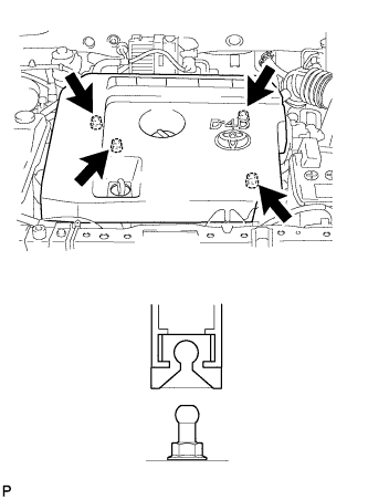
REMOVE NO. 1 ENGINE COVER
|
|
- Detach the 4 clips and remove the engine cover.
| 3.
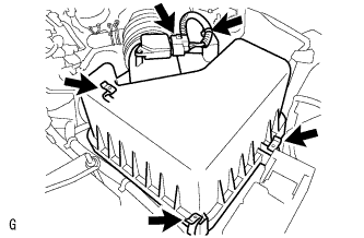
REMOVE AIR CLEANER ASSEMBLY |
|
- Disconnect the mass air flow meter connector.
Unhook the 3 hook clamps.
Disengage the wire harness clamp.
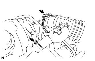
- Using pliers, grip the claws of the clip and slide the clip to disconnect the PCV hose from the cylinder head cover.
Using pliers, grip the claws of the clip to remove the air cleaner cap.
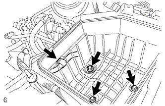
Remove the air filter element.
- Disconnect the wire harness clamp and remove the 3 bolts and air cleaner case.
| 4.
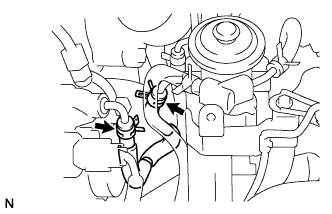
REMOVE NO. 3 FUEL HOSE |
|
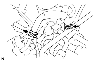
- Using pliers, grip the claws of the 2 clips and slide the 2 clips to remove the No. 3 fuel hose.
| 5.
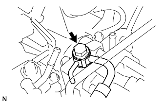
REMOVE FUEL TUBE SUB-ASSEMBLY |
|
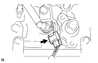
- Disconnect the exhaust fuel addition injector connector.
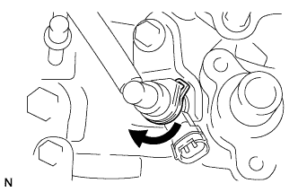
- Turn the retainer as shown in the illustration.
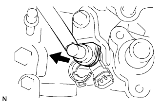
- Disconnect the fuel tube from the exhaust fuel addition injector connector.
- Remove the union bolt, gasket and fuel tube.
| 6.
REMOVE NO. 1 FUEL HOSE |
|
- Using pliers, grip the claws of the 2 clips and slide the 2 clips to remove the No. 1 fuel hose.
| 7.
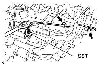
REMOVE FUEL INLET PIPE SUB-ASSEMBLY |
|
- NOTICE:
- After removing the fuel inlet pipe, cover the common rail and supply pump with electrical tape to prevent dirt from entering them.
- Remove the nut and fuel inlet pipe clamps.
Using SST, remove the fuel inlet pipe.
- SST
- 09023-38401
| 8.
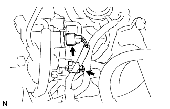
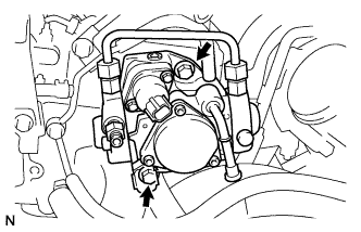
REMOVE FUEL SUPPLY PUMP ASSEMBLY |
|
- Disconnect the fuel temperature sensor connector.
Disconnect the suction control valve connector.
- Remove the 2 bolts to remove the supply pump, O-ring and supply pump drive coupling from the cylinder head.
Remove the O-ring from the supply pump.