DISASSEMBLY
Removal / installation · Vehicles built from Nov 2005
| 1. INSPECT 1ST DRIVEN GEAR THRUST CLEARANCE |

Using a dial indicator, measure the thrust clearance.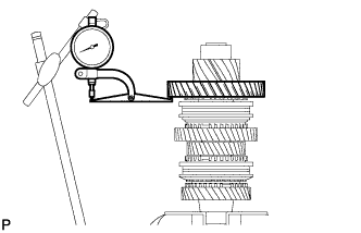

- Standard thrust clearance:
- 0.10 to 0.35 mm (0.0039 to 0.0138 in.)
- Maximum thrust clearance:
- 0.35 mm (0.0138 in.)
| 2. INSPECT 1ST DRIVEN GEAR RADIAL CLEARANCE |
Using a dial indicator, measure the radial clearance.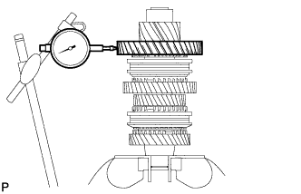
- Standard radial clearance:
- 0.015 to 0.068 mm (0.0006 to 0.0027 in.)
- Maximum clearance:
- 0.068 mm (0.0027 in.)
| 3. INSPECT 2ND DRIVEN GEAR THRUST CLEARANCE |
Using a dial indicator, measure the thrust clearance.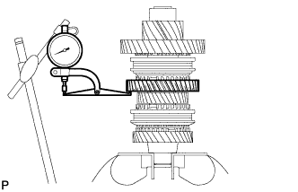
- Standard thrust clearance:
- 0.11 to 0.46 mm (0.0043 to 0.018 in.)
- Maximum thrust clearance:
- 0.46 mm (0.018 in.)
| 4. INSPECT 2ND DRIVEN GEAR RADIAL CLEARANCE |
Using a dial indicator, measure the radial clearance.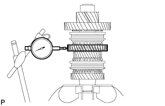
- Standard radial clearance:
- 0.015 to 0.048 mm (0.0006 to 0.0019 in.)
- Maximum radial clearance:
- 0.048 mm (0.0019 in.)
| 5. INSPECT 3RD DRIVEN GEAR THRUST CLEARANCE |
Using a feeler gauge, measure the thrust clearance.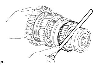
- Standard thrust clearance:
- 0.11 to 0.54 mm (0.0043 to 0.0213 in.)
- Maximum thrust clearance:
- 0.54 mm (0.0213 in.)
| 6. INSPECT 3RD DRIVEN GEAR RADIAL CLEARANCE |
Using a dial indicator, measure the radial clearance.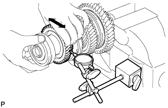
- Standard radial clearance:
- 0.015 to 0.066 mm (0.0006 to 0.0026 in.)
- Maximum radial clearance:
- 0.066 mm (0.0026 in.)
| 7. INSPECT 4TH DRIVEN GEAR THRUST CLEARANCE |
Using a feeler gauge, measure the thrust clearance.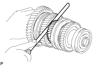
- Standard thrust clearance:
- 0.10 to 0.65 mm (0.0039 to 0.0256 in.)
- Maximum thrust clearance:
- 0.65 mm (0.0256 in.)
| 8. INSPECT 4TH DRIVEN GEAR RADIAL CLEARANCE |
Using a dial indicator, measure the radial clearance.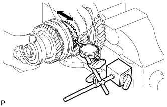
- Standard radial clearance:
- 0.015 to 0.066 mm (0.0006 to 0.0026 in.)
- Maximum radial clearance:
- 0.066 mm (0.0026 in.)
| 9. REMOVE OUTPUT SHAFT BEARING SHAFT SNAP RING |
Using a snap ring expander, remove the output shaft bearing shaft snap ring from the No. 1 output shaft.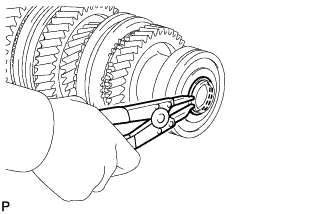
| 10. REMOVE OUTPUT SHAFT FRONT BEARING |
Using SST and press, press out the output shaft front bearing from the No. 1 output shaft.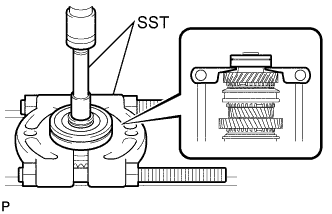
- SST
- 09201-31010
09950-00020
| 11. REMOVE 3RD DRIVEN GEAR |
Remove the 3rd driven gear from the No. 1 output shaft.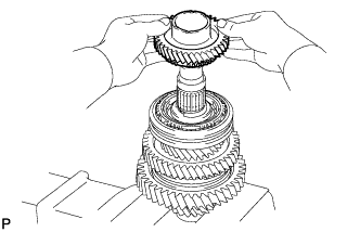
| 12. REMOVE SPACER |
Remove the spacer from the No. 1 output shaft.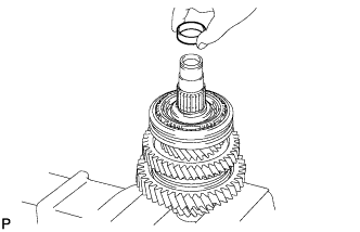
| 13. REMOVE NEEDLE ROLLER BEARING |
Remove the needle roller bearing from the No. 1 output shaft.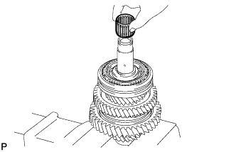
| 14. REMOVE 3RD DRIVEN GEAR SYNCHRONIZER RING SET |
Remove the synchronizer ring set from the No. 1 output shaft.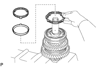
| 15. REMOVE SHAFT SNAP RING |
Using 2 screwdrivers and a hammer, tap out the shaft snap ring from the No. 1 output shaft.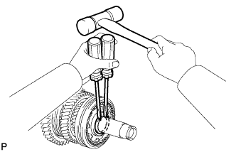
| 16. REMOVE 4TH DRIVEN GEAR |
Using SST and a press, press out the hub sleeve No. 2, 4th gear synchronizer ring set and 4th driven gear from the No. 1 output shaft.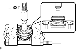
- SST
- 09950-00020
| 17. REMOVE 4TH DRIVEN GEAR SYNCHRONIZER RING SET |
Remove the 4th driven gear synchronizer ring set from the 4th driven gear.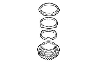
| 18. REMOVE NO. 2 TRANSMISSION CLUTCH HUB |
Remove the clutch hub, 3 keys, 3 balls and 3 key springs from the hub sleeve.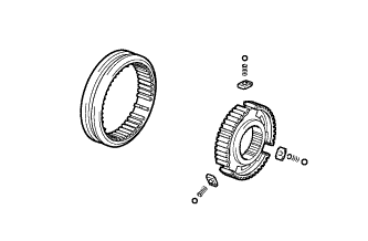
- NOTICE:
- Pay attention to prevent the balls and springs from scattering.
| 19. REMOVE NEEDLE ROLLER BEARING |
Remove the needle roller bearing from the No. 1 output shaft.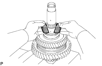
| 20. REMOVE SPACER |
Remove the spacer from the No. 1 output shaft.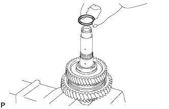
| 21. REMOVE OUTPUT SHAFT BEARING SHAFT SNAP RING |
Using a snap ring expander, remove the output shaft bearing shaft snap ring from the No. 1 output shaft.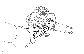
| 22. REMOVE 2ND GEAR BEARING INNER RACE |
Remove the 2nd gear bearing inner race from the No. 1 output shaft.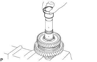
| 23. REMOVE 2ND DRIVEN GEAR |
Remove the 2nd driven gear from the No. 1 output shaft.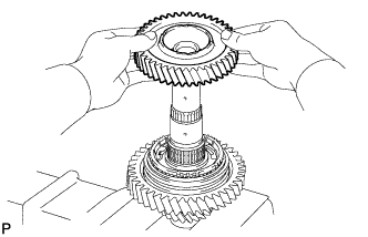
| 24. REMOVE NEEDLE ROLLER BEARING |
Remove the needle roller bearing from the No. 1 output shaft.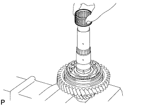
| 25. REMOVE SYNCHROMESH SHIFTING KEY BALL |
Remove the synchromesh shifting key ball from the No. 1 output shaft.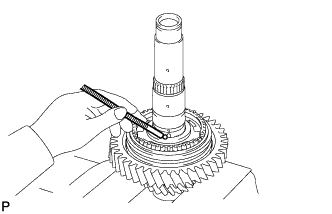
| 26. REMOVE 2ND DRIVEN GEAR SYNCHRONIZER RING SET |
Remove the synchronizer ring set from the No. 1 output shaft.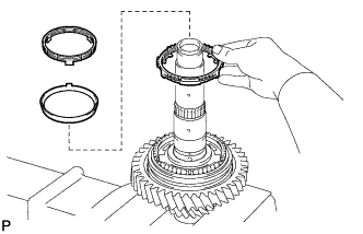
| 27. REMOVE 1ST DRIVEN GEAR |
Using SST and a press, press out the No. 1 hub sleeve, 1st driven gear synchronizer ring set and 1st driven gear from the No. 1 output shaft.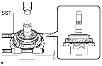
- SST
- 09950-00020
| 28. REMOVE 1ST DRIVEN GEAR SYNCHRONIZER RING SET |
Remove the synchronizer ring set from the 1st driven gear.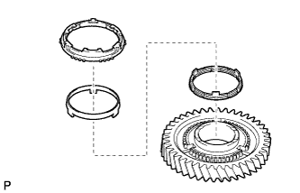
| 29. REMOVE NO. 1 TRANSMISSION CLUTCH HUB |
Remove the clutch hub, 3 keys, 3 balls and 3 key springs from the hub sleeve.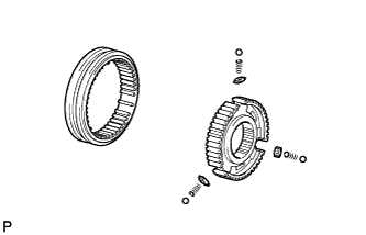
- NOTICE:
- Pay attention to prevent the balls and springs from scattering.
| 30. REMOVE NEEDLE ROLLER BEARING |
Remove the needle roller bearing from the No. 1 output shaft.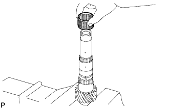
| 31. REMOVE OUTPUT SHAFT FRONT BEARING SHAFT SNAP RING |
Using a snap ring expander, remove the output shaft front bearing shaft snap ring from the No. 1 output shaft.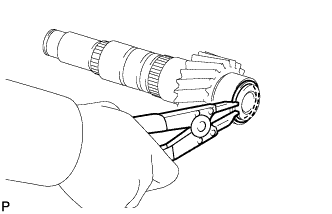
| 32. REMOVE OUTPUT SHAFT FRONT BEARING |
Using SST and a press, press out the output shaft front bearing from the No. 1 output shaft.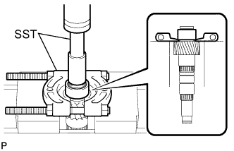
- SST
- 09201-31010
09950-00020
| 33. INSPECT 5TH DRIVEN GEAR THRUST CLEARANCE |
Using a feeler gauge, measure the thrust clearance.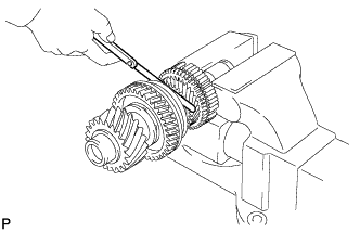
- Standard thrust clearance:
- 0.10 to 0.55 mm (0.0039 to 0.0217 in.)
- Maximum thrust clearance:
- 0.55 mm (0.0217 in.)
| 34. INSPECT 5TH DRIVEN GEAR RADIAL CLEARANCE |
Using a dial indicator, measure the radial clearance.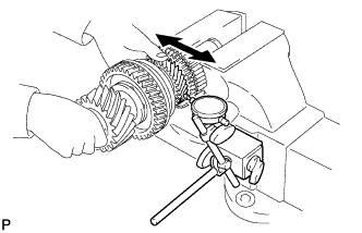
- Standard radial clearance:
- 0.015 to 0.066 mm (0.0006 to 0.0026 in.)
- Maximum radial clearance:
- 0.066 mm (0.0026 in.)
| 35. INSPECT 6TH DRIVEN GEAR THRUST CLEARANCE |
Using a feeler gauge, measure the thrust clearance.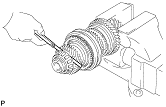
- Standard thrust clearance:
- 0.10 to 0.55 mm (0.0039 to 0.0217 in.)
- Maximum thrust clearance:
- 0.55 mm (0.0217 in.)
| 36. INSPECT 6TH DRIVEN GEAR RADIAL CLEARANCE |
Using a dial indicator, measure the radial clearance.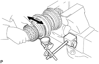
- Standard radial clearance:
- 0.015 to 0.066 mm (0.0006 to 0.0026 in.)
- Maximum radial clearance:
- 0.066 mm (0.0026 in.)
| 37. INSPECT REVERSE DRIVEN GEAR THRUST CLEARANCE |
Using a feeler gauge, measure the thrust clearance.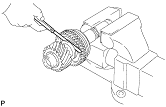
- Standard thrust clearance:
- 0.11 to 0.34 mm (0.0043 to 0.0134 in.)
- Maximum thrust clearance:
- 0.34 mm (0.0134 in.)
| 38. INSPECT REVERSE DRIVEN GEAR RADIAL CLEARANCE |
Using a dial indicator, measure the gear radial clearance.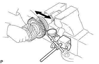
- Standard radial clearance:
- 0.015 to 0.068 mm (0.0006 to 0.0027 in.)
- Maximum radial clearance:
- 0.068 mm (0.0027 in.)
| 39. REMOVE NO. 2 OUTPUT SHAFT BEARING SNAP RING |
Using a snap ring expander, press out the No. 2 output shaft bearing snap ring from the No. 2 output shaft.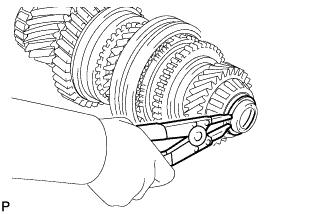
| 40. REMOVE NO. 2 OUTPUT SHAFT REAR BEARING |
Using SST and a press, remove the No. 2 output shaft rear bearing and 6th driven gear from the No. 2 output shaft.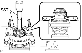
- SST
- 09201-31010
09950-00020
| 41. REMOVE NEEDLE ROLLER BEARING |
Remove the needle roller bearing from the No. 2 output shaft.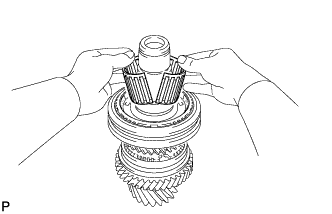
| 42. REMOVE SPACER |
Remove the spacer from the No. 2 output shaft.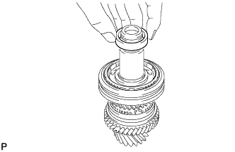
| 43. REMOVE 6TH GEAR SYNCHRONIZER RING |
Remove the 6th gear synchronizer ring from the No. 2 output shaft.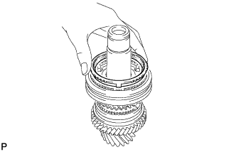
| 44. REMOVE SHAFT SNAP RING |
Using 2 screwdrivers and a hammer, tap out the shaft snap ring from the No. 2 output shaft.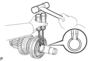
| 45. REMOVE 5TH DRIVEN GEAR |
Using SST and a press, press out the No. 3 hub sleeve, 5th synchronizer ring and 5th driven gear from the No. 2 output shaft.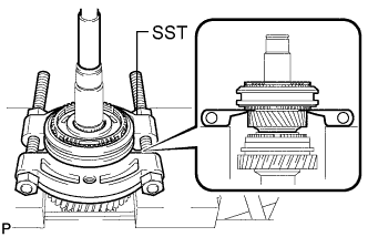
- SST
- 09950-00020
| 46. REMOVE 5TH DRIVEN GEAR SYNCHRONIZER RING |
Remove the 5th driven gear synchronizer ring from the 5th driven gear.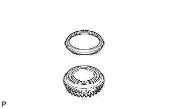
| 47. REMOVE NO. 3 TRANSMISSION CLUTCH HUB |
Remove the No. 3 clutch hub, 3 keys, 3 balls and 3 key springs from the hub sleeve.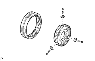
- NOTICE:
- Pay attention to prevent the balls and springs from scattering.
| 48. REMOVE SHAFT SNAP RING |
Using 2 screwdrivers and a hammer, remove the shaft snap ring from the No. 2 output shaft.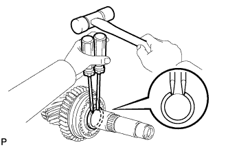
| 49. REMOVE REVERSE DRIVEN GEAR |
Using SST and a press, press out the No. 4 hub sleeve, reverse gear synchronizer ring set and reverse driven gear from the No. 2 output shaft.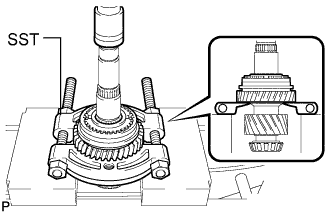
- SST
- 09950-00020
| 50. REMOVE REVERSE DRIVEN GEAR SYNCHRONIZER RING |
Remove the reverse driven gear synchronizer ring from the reverse gear.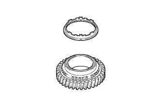
| 51. REMOVE NO. 4 TRANSMISSION CLUTCH HUB |
Remove the No. 4 transmission clutch hub, synchromesh shifting key spring and 2 synchromesh shifting keys from the transmission hub sleeve.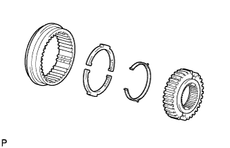
| 52. REMOVE NEEDLE ROLLER BEARING |
Remove the needle roller bearing from the No. 2 output shaft.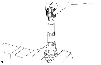
| 53. REMOVE NO. 2 OUTPUT SHAFT FRONT BEARING |
Using SST and a press, press out the No. 2 output shaft front bearing from the No. 2 output shaft.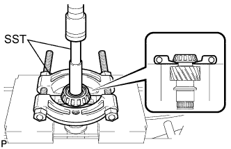
- SST
- 09201-31010
09950-00020