REMOVAL
Removal / installation · Vehicles built Jan 2007 – Jul 2007
Versions by build date: Nov 2005 – Dec 2006 Jan 2007 – Jul 2007 from Aug 2007
| 1. DISCHARGE FUEL SYSTEM PRESSURE |

- CAUTION:
- DISCHARGE FUEL SYSTEM PRESSURE procedures must be performed before disconnecting any part of the fuel system.
- After performing the DISCHARGE FUEL SYSTEM PRESSURE procedures, pressure will remain in the fuel line. When disconnecting the fuel line, place a cloth or equivalent over fittings to reduce the risk of fuel spray.
- DISCHARGE FUEL SYSTEM PRESSURE procedures must be performed before disconnecting any part of the fuel system.
Remove the console box (Click here).
Disconnect the connector.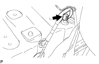

Start the engine. After the engine has stopped, turn the ignition switch off.
- HINT:
- DTC P0171 (system too lean) may be set.
Check that the engine does not start.
Remove the fuel tank cap, and let the air out of the fuel tank.
Connect the connector.
Install the console box (Click here).
| 2. DRAIN COOLANT |
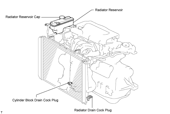
Loosen the radiator drain cock plug.
- HINT:
- Collect the coolant in a container and dispose of it according to the regulations in your area.
Remove the radiator reservoir cap.
- CAUTION:
- Do not remove the radiator reservoir cap while the engine and radiator are still hot. Pressurized, hot engine coolant and steam may be released and cause serious burns.
Loosen the cylinder block drain cock plug.
| 3. DISCONNECT CABLE FROM NEGATIVE BATTERY TERMINAL |
- CAUTION:
- Wait at least 90 seconds after disconnecting the cable from the negative (-) battery terminal to prevent airbag and seat belt pretensioner activation.
| 4. REMOVE NO. 1 ENGINE COVER |
Remove the 2 nuts and engine cover.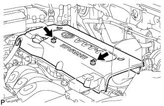
| 5. REMOVE AIR CLEANER CAP |
Disconnect the mass air flow meter connector.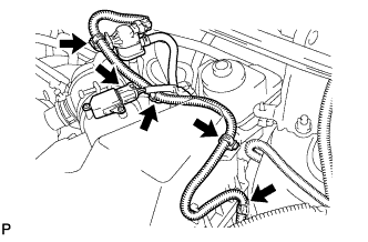
Disconnect the purge VSV connector.
Disconnect the 4 wire harness clamps.
Disconnect the No. 2 ventilation hose from the air cleaner hose.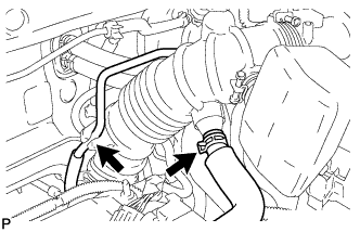
Disconnect the purge line hose from the clamp.
Squeeze the tabs of the No. 1 air cleaner hose clamp, and then disconnect the No. 1 air cleaner hose from the throttle body.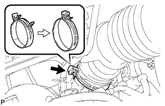
Unfasten the 2 hook clamps, and then remove the air cleaner cap.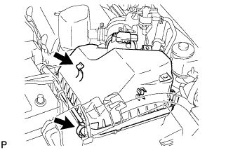
Remove the air cleaner filter element from the air cleaner case.
| 6. REMOVE THROTTLE BODY |
Disconnect the purge line hose from the throttle body.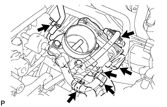
Disconnect the water by-pass hose from the throttle body.
Disconnect the No. 2 water by-pass hose from the throttle body.
Disconnect the No. 1 throttle body hose from the throttle body.
Disconnect the throttle position sensor and control motor connector.
Disconnect the wire harness clamp.
Disconnect the fuel tube from the clamp.
Remove the 4 bolts, and then remove the fuel pipe support and throttle body.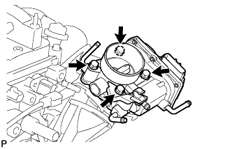
Remove the gasket from the intake manifold.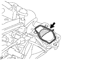
| 7. DISCONNECT FUEL TUBE |
 |
- NOTICE:
- Do not forcibly bend and twist the fuel main tube.
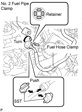
Remove the fuel tube from the fuel hose clamp.
Remove the fuel pipe clamp.
Wipe off any dirt on the fuel tube connector.
Hold the fuel tube connector, and then install the SST.
- SST
- 09268-21010
Turn the SST to align the retainer inside the fuel tube connector with the chamfered part of the SST.
Insert the SST into the fuel tube and hold it. Then push the fuel tube connector toward the SST side.
Mount the retainer of the fuel tube connector onto the chamfered part of the SST.
Slide the SST and fuel tube connector together towards the fuel tube until they make a "click" sound, and then disconnect the fuel tube.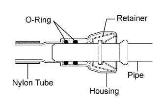
Drain the fuel remaining inside the fuel tube.
Cover the fuel tube and fuel pipe with a plastic bag to protect the disconnected part.
| 8. REMOVE FUEL DELIVERY PIPE |
Remove the 2 wire harness clamps.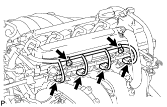
Disconnect the 4 fuel injector connectors.
Remove the 2 bolts and then pull out the fuel delivery pipe together with the 4 fuel injectors.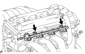
- NOTICE:
- Be careful not to drop the fuel injectors when removing the fuel delivery pipe.
Remove the 2 delivery pipe spacers from the cylinder head.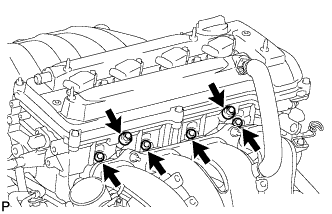
Remove the 4 insulators from the cylinder head.
| 9. REMOVE HEATER WATER INLET HOSE |
Remove the hose clamp.
Remove the heater water inlet hose from the heater radiator unit and cylinder head.
| 10. REMOVE HEATER WATER OUTLET HOSE |
Remove the heater water outlet hose from the heater radiator unit and water by-pass pipe.
| 11. REMOVE INTAKE MANIFOLD |
Disconnect the union to check valve hose from the brake booster.
Disconnect the camshaft timing oil control valve connector.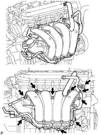
Remove the wire harness clamp.
Remove the union to check valve hose from the vacuum hose clamp.
Remove the 5 bolts, 2 nuts and intake manifold.
Remove the gasket from the intake manifold.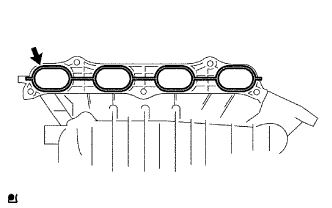
| 12. REMOVE INTAKE MANIFOLD INSULATOR |
Remove the intake manifold insulator from the cylinder block.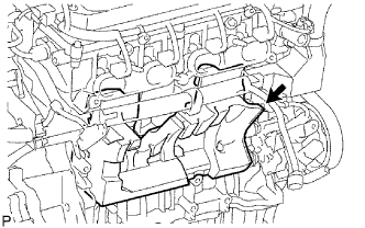
| 13. REMOVE KNOCK SENSOR |
Disconnect the sensor connector.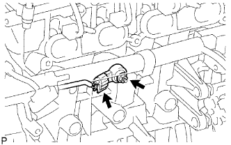
Remove the nut and sensor.