Home › BODY › INSTRUMENT PANEL › LOWER INSTRUMENT PANELINSTALLATION
Removal / installation · Vehicles built Jan 2007 – Jul 2007
Versions by build date: Nov 2005 – Dec 2006 Jan 2007 – Jul 2007 Aug 2007 – Jul 2008 from Aug 2008
1.
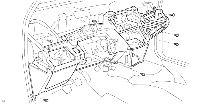
INSTALL LOWER INSTRUMENT PANEL
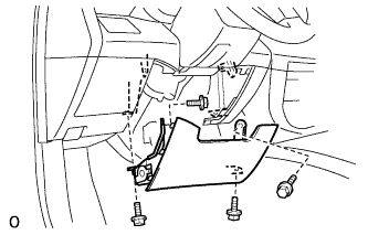
Connect the connectors and clamps and install the lower instrument panel.
Install the 2 bolts, 3 screws and 2 clips.
2.
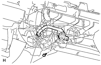
INSTALL NO. 6 HEATER TO REGISTER DUCT ASSEMBLY (w/ Cool Box)
Install the duct with the 2 screws.
3.
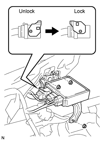
INSTALL POWER STEERING ECU ASSEMBLY
Install the ECU with the 3 nuts.
Connect the connectors.
4.
INSTALL INSTRUMENT PANEL BOX
Attach the 6 clips to install the instrument panel box.
Install the screw.
5.
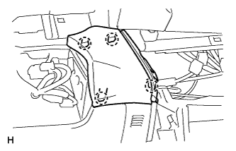
INSTALL INSTRUMENT PANEL SAFETY PAD COVER (for LHD)
Attach the 4 claws to install the instrument panel safety pad cover.
6.
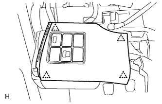
INSTALL NO. 1 SWITCH HOLE BASE
Connect the connectors.
Attach the 4 clips to install the switch hole base.
7.
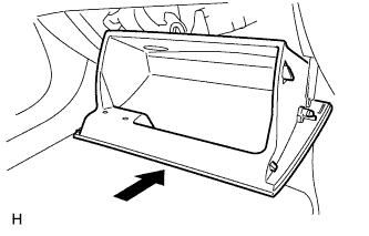
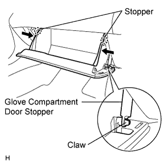
INSTALL GLOVE COMPARTMENT DOOR ASSEMBLY
Attach the 2 hinges to install the door.
Attach the claw to the glove compartment door stopper. While pushing in the sides of the glove compartment door as indicated by the arrows in the illustration, close the door to engage it to the 2 stoppers.
8.
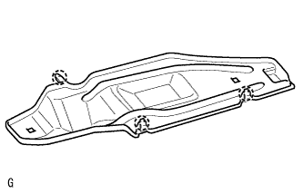
INSTALL NO. 2 INSTRUMENT PANEL UNDER COVER SUB-ASSEMBLY (w/ Knee Airbag)
Attach the 2 claws to install the instrument panel under cover.
9.
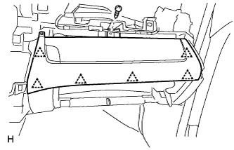
INSTALL LOWER INSTRUMENT PANEL FINISH PANEL (w/o Knee Airbag)
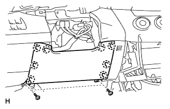
Attach the 8 claws to install the lower instrument panel finish panel.
Install the 2 screws.
10.
INSTALL DRIVER SIDE KNEE AIRBAG ASSEMBLY (w/ Knee Airbag)
Connect the connector.
NOTICE:
When handling the airbag connector, take care not to damage the airbag wire harness.
Install the driver side knee airbag with the 4 bolts.
Torque:
10 N*m{
101 kgf*cm
, 7 ft.*lbf
}
11.
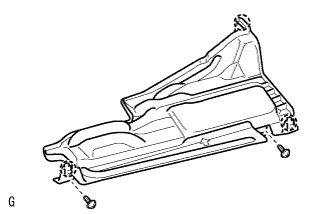
INSTALL NO. 1 INSTRUMENT PANEL UNDER COVER SUB-ASSEMBLY (w/ Knee Airbag)
Attach the 2 claws to install the instrument panel under cover.
Install the 2 screws.
12.
INSTALL REAR CONSOLE BOX SUB-ASSEMBLY
Connect the connector.
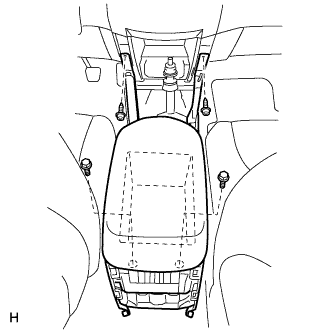
Install the rear console box with the 2 bolts and 2 screws.
Install the console box carpet.
13.
INSTALL NO. 1 INSTRUMENT PANEL BRACKET COVER INNER LH
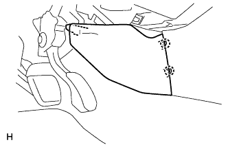
Attach the 2 claws to install the instrument panel bracket cover.
14.
INSTALL NO. 1 INSTRUMENT PANEL BRACKET COVER INNER RH
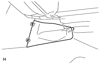
Attach the 2 claws to install the instrument panel bracket cover.
15.
INSTALL CONSOLE REAR END PANEL
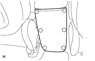
Attach the 6 claws to install the console rear end panel.
16.
INSTALL UPPER REAR CONSOLE PANEL SUB-ASSEMBLY
Connect the connector.
Attach the 4 clips to install the upper rear console panel.
17.
INSTALL CONSOLE CUP HOLDER BOX
Attach the 2 clips to install the cup holder box.
Install the 2 screws.
18.
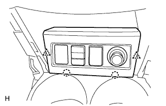
INSTALL SWITCH BASE
Connect the connectors.
Attach the 2 clips and 2 claws to install the switch base.
19.
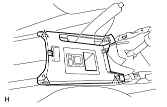
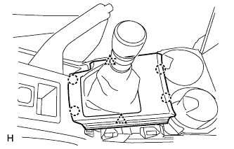
INSTALL UPPER CONSOLE PANEL SUB-ASSEMBLY
Automatic transaxle: Connect the connector.
Attach the 2 clips and 4 claws to install the upper console panel.
Install the shift lever knob.
20.
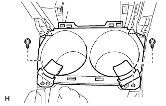
INSTALL NO. 2 CONSOLE UPPER PANEL GARNISH
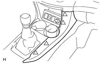
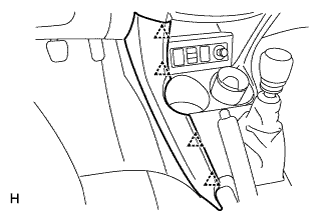
Attach the 4 clips to install the upper panel garnish.
21.
INSTALL NO. 1 CONSOLE UPPER PANEL GARNISH
Attach the 4 clips to install the upper panel garnish.
22.
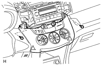
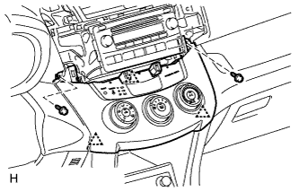
INSTALL HEATER CONTROL SUB-ASSEMBLY (for Automatic Air Conditioning System)
Connect the connectors. Attach the 3 clips to install the air conditioning control.
Install the 2 screws.
23.
INSTALL HEATER CONTROL SUB-ASSEMBLY (for Manual Air Conditioning System)
Connect the connectors. Attach the 3 clips to install the air conditioning control.
Install the 2 screws.
24.
INSTALL WINDSHIELD WIPER SWITCH ASSEMBLY
25.
INSTALL HEADLIGHT DIMMER SWITCH ASSEMBLY
26.
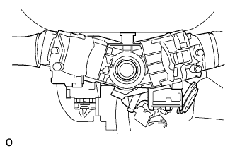
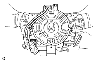
INSTALL SPIRAL CABLE SUB-ASSEMBLY
Check that the front wheels are facing straight ahead.
Set the turn signal switch to the neutral position.
NOTICE:
Make sure that the turn signal switch is in the neutral position, as the pin of the turn signal switch may be snapped.
Install the spiral cable.
NOTICE:
When replacing the spiral cable with a new one, remove the lock pin before installing the steering wheel.
Connect the connectors to the spiral cable.
NOTICE:
When handling the airbag connector, do not damage the airbag wire harness.
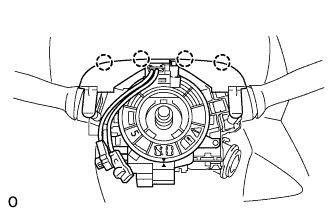
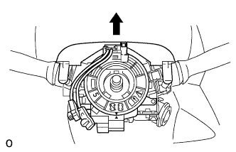
Attach the 4 clips to the column cover (upper).
Install the steering column cover (upper).
27.
INSTALL STEERING COLUMN COVER
for LHD (Click here ) for RHD (Click here )
28.
INSTALL STEERING WHEEL ASSEMBLY
for LHD (Click here ) for RHD (Click here )
29.
INSTALL STEERING PAD ASSEMBLY
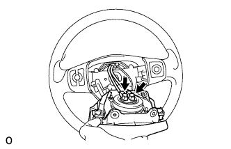
Support the steering pad with one hand as shown in the illustration.
Connect the 2 airbag connectors.
NOTICE:
When handling the airbag connector, do not damage the airbag wire harness.
Connect the horn connector.
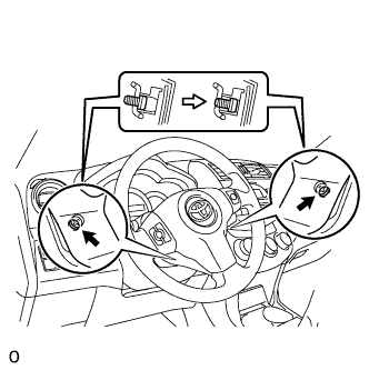
Install the steering pad after confirming that the circumference grooves of the screws are caught on the screw case.
Using a T30 "torx" driver, install the 2 screws.
Torque:
8.8 N*m{
90 kgf*cm
, 78 in.*lbf
}
30.
INSTALL INSTRUMENT PANEL SUB-ASSEMBLY
Install the instrument panel (Click here ).
31.
CONNECT CABLE TO NEGATIVE BATTERY TERMINAL
32.
CHECK SRS WARNING LIGHT
Check the SRS warning light (Click here ).