TERMINALS OF ECM
System information · Vehicles built Nov 2005 – Jul 2007
Versions by build date: Nov 2005 – Jul 2007 from Aug 2007
| CHECK ECM |
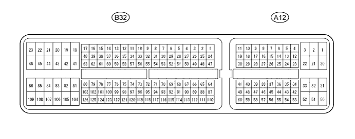

Disconnect the A12 and B32 connectors.
Measure the voltage and resistance of the wire harness side connectors.
Symbols (Terminal No.)
Wiring Color
Terminal Description
Condition
Specified Condition
STP (A12-36) - E1 (B32-104)*1
STP (A12-35) - E1 (B32-109)*2
L - BR
Stop light switch input signal
Depress brake pedal
10 to 14 V
Release brake pedal
Below 1 V
CCS (A12-40) - E1 (B32-104)*1
CCS (A12-23) - E1 (B32-109)*2
L - BR
Cruise control main switch signal
CANCEL switch hold ON
1.386 to 1,694 Ω
-/SET switch hold ON
567 to 693 Ω
+/RES switch hold ON
216 to 264 Ω
Main switch OFF
10 kΩ or higher
Main switch ON
Below 1 Ω
ST1- (A12-35) - E1 (B32-104)*1
ST1- (A12-34) - E1 (B32-109)*2
GR - BR
Stop light switch input signal
Release brake pedal
10 to 14 V
Depress brake pedal
Below 1 V
D (B32-56) - E1 (B32-104)*1, *3
CLSW (A12-42) - E1 (B32-109)*2, *3
B - BR
Cruise control clutch switch input signal
Cruise control clutch switch is ON
10 to 14 V
Cruise control clutch switch is OFF
Below 1 V
- HINT:
- *1: for 1AZ-FE, 2AZ-FE
- *2: for 2AD-FTV, 2AD-FHV
- *3: for M/T