TERMINALS OF ECM
System information · Vehicles built from Aug 2007
Versions by build date: Nov 2005 – Jul 2007 from Aug 2007
| CHECK ECM |
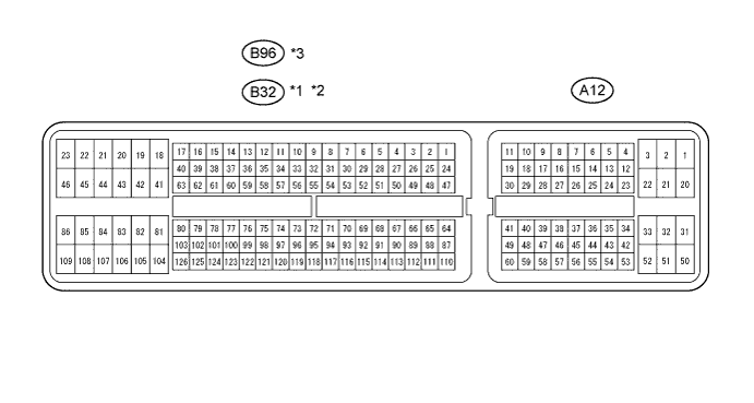

Disconnect the A12 and B32 or B96 connectors.
Measure the voltage and resistance of the wire harness side connectors.
Symbols (Terminal No.)
Wiring Color
Terminal Description
Condition
Specified Condition
STP (A12-36) - E1 (B32-104)*1
STP (A12-35) - E1 (B32-109)*2
STP (A12-36) - E1 (B96-81)*3
L - BR
Stop light switch input signal
Depress brake pedal
10 to 14 V
Release brake pedal
Below 1 V
CCS (A12-40) - E1 (B32-104)*1
CCS (A12-23) - E1 (B32-109)*2
CCS (A12-40) - E1 (B96-81)*3
L - BR
Cruise control main switch signal
CANCEL switch held ON
1.386 to 1,694 Ω
-/SET switch held ON
567 to 693 Ω
+/RES switch held ON
216 to 264 Ω
Main switch OFF
10 kΩ or higher
Main switch ON
Below 1 Ω
ST1- (A12-35) - E1 (B32-104)*1
ST1- (A12-34) - E1 (B32-109)*2
ST1- (A12-35) - E1 (B96-81)*3
GR - BR
Stop light switch input signal
Release brake pedal
10 to 14 V
Depress brake pedal
Below 1 V
D (B32-56) - E1 (B32-104)*1, *4
CLSW (A12-42) - E1 (B32-109)*2, *4
B - BR
Cruise control clutch switch input signal
Cruise control clutch switch is ON
10 to 14 V
Cruise control clutch switch is OFF
Below 1 V
- HINT:
- *1: for 1AZ-FE, 2AZ-FE
- *2: for 2AD-FTV, 2AD-FHV
- *3: for 2GR-FE
- *4: for M/T