INSPECTION
Removal / installation · Vehicles built from Nov 2005
| 1. INSPECT OUTPUT SHAFT |

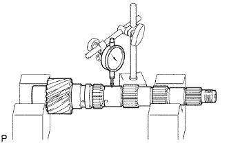  |
Using V-blocks and a dial indicator, measure the shaft for runout.
- Maximum runout:
- 0.03 mm (0.0012 in.)
Using a micrometer, measure the diameter of the output shaft journal surface.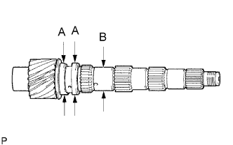
- Standard diameter:
Journal Position
Specified Condition
A
37.610 to 37.626 mm (1.4807 to 1.4813 in.)
B
34.502 to 34.512 mm (1.3583 to 1.3587 in.)
- Minimum diameter:
Journal Position
Specified Condition
A
37.610 mm (1.4803 in.)
B
34.502 mm (1.3583 in.)
| 2. INSPECT 2ND GEAR |
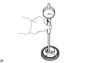 |
Using a cylinder gauge, measure the inside diameter.
- Standard inside diameter:
- 50.009 to 50.025 mm (1.9689 to 50.025 in.)
- Maximum inside diameter:
- 50.025 mm (1.9695 in.)
| 3. INSPECT 1ST GEAR |
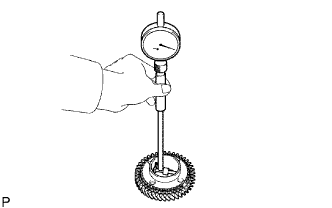 |
Using a cylinder gauge, measure the inside diameter.
- Standard inside diameter:
- 51.009 to 51.025 mm (51.009 to 51.0525 in.)
- Maximum inside diameter:
- 51.025 mm (2.0089 in.)
| 4. INSPECT NO. 2 SYNCHRONIZER RING SET |
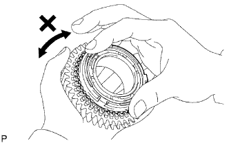 |
Coat the 2nd gear cone with gear oil. Turn the No. 2 synchronizer ring set in one direction while pushing it against the No. 2 synchronizer ring set. Check that the ring locks.
If the No. 2 synchronizer ring set does not lock, replace the synchronizer ring or 2nd gear.
Check the clearance between the No. 2 synchronizer ring set and 2nd gear while pushing the 2nd gear against the No. 2 synchronizer ring set.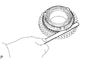
- Standard clearance:
- 0.70 to 1.45 mm (0.0276 to 0.0571 in.)
| 5. INSPECT NO. 1 SYNCHRONIZER RING SET |
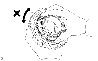 |
Coat the 1st gear cone with gear oil. Turn the No. 1 synchronizer ring set in one direction while pushing it against the 1st gear cone. Check that the ring locks.
If the No. 1 synchronizer ring set does not lock, replace it with a new one.
Check the clearance between the No. 1 synchronizer ring set and 1st gear while pushing the 1st gear against the cone of the No. 1 synchronizer ring set.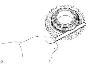
- Standard clearance:
- 0.70 to 1.45 mm (0.0276 to 0.0571 in.)
| 6. INSPECT REVERSE GEAR |
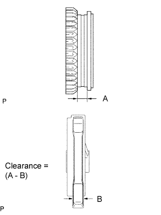 |
Using a vernier caliper, measure the width of the reverse gear groove (A) and thickness of the claw part on the No. 1 gear shift fork (B), and calculate the clearance.
- Standard clearance:
- A - B = 0.15 to 0.35 mm (0.0276 to 0.0571 in.)
| 7. INSPECT NO. 1 TRANSAXLE CLUTCH HUB |
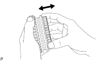 |
Check the sliding condition between the No. 1 transaxle clutch hub and the reverse gear.
Check the tip of the spline gear on the sleeve of the reverse gear for wear.
If any defects are found, replace the reverse gear or the No. 1 transaxle clutch hub.