Symbols (Terminal No.)
|
Wiring Color
|
Terminal Description
|
Condition
|
Specified Condition
|
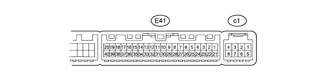
B (E41-21) - GND (E41-14)
|
R - W-B
|
Power source (Back-up)
|
Always
|
10 to 14 V
|
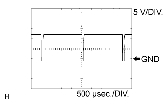
SOL+ (E41-2) - GND (E41-14)
|
GR - W-B
|
A/C compressor operation signal
|
Engine idling
|
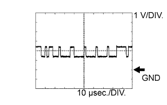
Pulse generation
(see waveform 1)
|
Blower switch LO
|
A/C switch ON
|
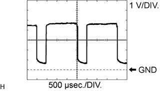
BLW (E41-23) - GND (E41-14)
|
R - W-B
|
Blower motor control signal
|
Ignition switch on (IG)
|
Pulse generation
(see waveform 2)
|
Blower switch LO
|
PRE (E41-9) - SG-2 (E41-13)
|
L - G
|
Air conditioning pressure sensor signal
|
Refrigerant pressure: normal
|
0.76 to 4.74 V
|
PRE (E41-9) - SG-2 (E41-13)
|
L - G
|
Air conditioning pressure sensor signal
|
Refrigerant pressure: Abnormal (less than 0.196 MPa [2.0 kgf/cm2, 28 psi])
|
Below 0.76 V
|
PRE (E41-9) - SG-2 (E41-13)
|
L - G
|
Air conditioning pressure sensor signal
|
Refrigerant pressure: Abnormal (more than 3.14 MPa [32 kgf/cm2, 455 psi])
|
4.74 V or higher
|
TSD (E41-33) - S5-4 (E41-31)
|
L - LG
|
Driver side solar sensor signal
|
Ignition switch on (IG)
|
0.8 to 4.3 V
|
Solar sensor subject to electric light
|
TSP (E41-32) - S5-4 (E41-31)
|
P - LG
|
Passenger side solar sensor signal
|
Ignition switch on (IG)
|
0.8 to 4.3 V
|
Solar sensor subject to electric light
|
TR (E41-29) - SG-1 (E41-34)
|
CR- V
|
Room temperature sensor signal
|
Ignition switch on (IG)
|
1.8 to 2.2 V
|
Vehicle interior temperature: 25°C (77°F)
|
SG-1 (E41-34) - Body ground
|
V - Body ground
|
Ground for room temperature sensor
|
Always
|
Below 1 Ω
|
GND (E41-14) - Body ground
|
W-B - Body ground
|
Ground for main power supply
|
Always
|
Below 1 Ω
|
IG+ (E41-1) - GND (E41-14)
|
Y - W-B
|
Power source (IG)
|
Ignition switch on (IG)
|
10 to 14 V
|
S5-3 (E41-10) - GND (E41-14)
|
B - W-B
|
Power supply for pressure sensor
|
Ignition switch on (IG)
|
4.5 to 5.5 V
|
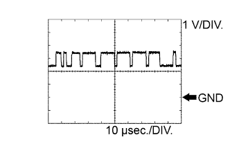
CANH (E41-11) - GND (E41-14)
|
V - W-B
|
Hi-level CAN bus line
|
Ignition switch on (IG)
|
Pulse generation
(see waveform 3)
|
CANL (E41-12) - GND (E41-14)
|
W - W-B
|
Lo-level CAN bus line
|
Ignition switch on (IG)
|
Pulse generation
(see waveform 4)
|
RDEF (E41-38) - GND (E41-14)
|
B - W-B
|
Rear defogger switch signal
|
Ignition switch on (IG)
Rear defogger switch OFF
|
10 to 14 V
|
RDEF (E41-38) - GND (E41-14)
|
B - W-B
|
Rear defogger switch signal
|
Ignition switch on (IG)
Rear defogger switch ON
|
Below 1 Ω
|
SG-2 (E41-13) - Body ground
|
B - Body ground
|
Ground for pressure sensor
|
Always
|
Below 1 Ω
|
PTC1 (E41-3)* - Body ground
|
W - Body ground
|
PTC NO. 1 heater relay operation signal
|
Engine idling
|
Below 1 V → 10 to 14 V
|
Set temperature: MAX HOT
|
Engine coolant temperature: Below 65°C (149°F)
|
Ambient temperature: Below 10°C (50°F)
|
Blower switch OFF → LO
|
PTC2 (E41-22)* - Body ground
|
B - Body ground
|
PTC NO. 2 heater relay operation signal
|
Engine idling
|
Below 1 V → 10 to 14 V
|
Set temperature: MAX HOT
|
Engine coolant temperature: Below 65°C (149°F)
|
Ambient temperature: Below 10°C (50°F)
|
Blower switch OFF → LO
|
ALT (E41-25)* - Body ground
|
B - Body ground
|
Generator signal
|
Engine idling
|
Pulse generation
|
HLS (E41-27)* - Body ground
|
BR - Body ground
|
Headlight signal
|
Engine idling
|
Below 1 Ω
|
Headlight switch ON
|
LIN1 (E41-37) - GND (E41-14)
|
B - W-B
|
LIN communication signal
|
Ignition switch on (IG)
|
Pulse generation
|
BUS G (c1-2) - Body ground
|
-
|
Ground for BUS IC
|
Always
|
Below 1 Ω
|
BUS (c1-3) - BUS G (c1-2)
|
-
|
BUS IC control signal
|
Ignition switch on (IG)
|
Pulse generation
|
B BUS (c1-4) - BUS G (c1-2)
|
-
|
Power supply for BUS IC
|
Ignition switch on (IG)
|
11 to 13 V
|
SGA (c1-5) - Body ground
|
-
|
Ground for evaporator temperature sensor
|
Always
|
Below 1 Ω
|
TEA (c1-6) - SGA (c1-5)
|
-
|
Evaporator temperature sensor signal
|
Ignition switch on (IG)
|
1.4 to 1.8 V
|
Evaporator temperature: 15°C (59°F)
|