C1380/64 Stop Light Control Relay Malfunction
Diagnostic trouble codes · Vehicles built Aug 2007 – Jul 2008
Versions by build date: Nov 2005 – Dec 2006 Jan 2007 – Jul 2007 Aug 2007 – Jul 2008
DESCRIPTION
The skid control ECU inputs the stop light switch signal and detects the status of the brake operation.| DTC No. |
DTC Detection Condition |
Trouble Area |
| C1380/64 |
When one of following conditions is met:
|
|
WIRING DIAGRAM
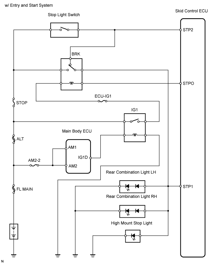

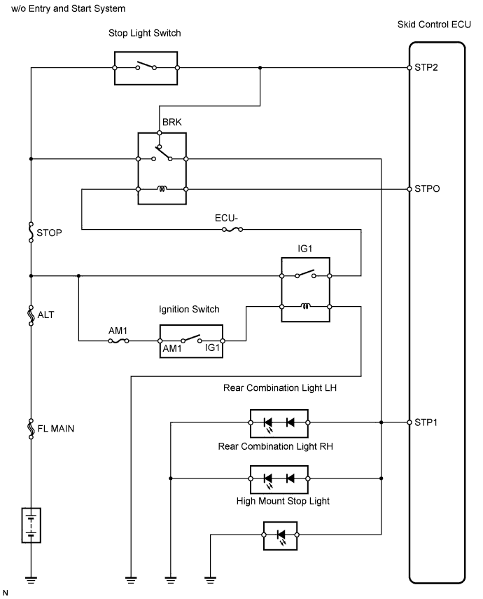
INSPECTION PROCEDURE
- NOTICE:
- When replacing the ABS and TRACTION actuator, perform zero point calibration (Click here).
| 1. CHECK STOP LIGHT (OPERATION) |

Check that the light illuminates when the brake pedal is depressed, and turns off when the brake pedal is released.
OK Condition
Stop Light Condition
Brake pedal depressed
Illuminates
Brake pedal released
Turn off
|
|
||||

| OK | |
 |
| 2. CHECK WIRE HARNESS (SKID CONTROL ECU - BATTERY) |
Disconnect the A26 ECU connector.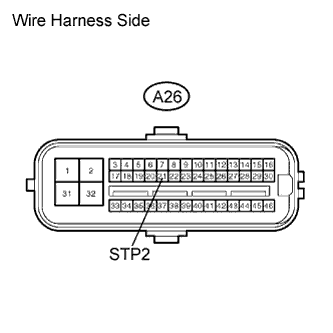
Measure the voltage of the wire harness side connector.
- Standard voltage:
Tester Connection
Switch Condition
Specified Condition
A26-21 (STP2) - Body ground
Brake pedal depressed
8 to 16 V
A26-21 (STP2) - Body ground
Brake pedal released
Below 1.5 V
|
|
||||

| OK | |
|
| 3. CHECK WIRE HARNESS (SKID CONTROL ECU) |
Disconnect the A26 ECU connector.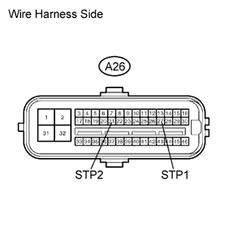
Measure the resistance of the wire harness side connector.
- Standard resistance:
Tester Connection
Specified Condition
A26-21 (STP2) - A26-27 (STP1)
Below 1 Ω
|
|
||||
| OK | |
|
| 4. PERFORM ACTIVE TEST USING INTELLIGENT TESTER (STOP LIGHT RELAY) |
Select the Active Test, generate a control command, and then check that the stop light relay operates.
Skid control ECU Item
Test Details
Diagnosis Note
Stop Lamp Relay
Turn stop light relay ON / OFF
Observe stop light
- OK:
- The stop lights illuminate or turn off.
|
|
||||
| OK | |
|
| 5. RECONFIRM DTC |
Clear the DTC (Click here).
Start the engine.
Drive the vehicle at a speed of 5 km/h (3 mph) or more for several seconds.
Check if the same DTC is output (Click here).
Result Result
Proceed to
DTC is output
A
DTC is not output
B
|
|
||||
| A | ||
 |
||
| ||
| 6. INSPECT STOP LIGHT CONTROL RELAY (Marking: BRK) |
Remove the stop light control relay from the engine room No. 1 relay block.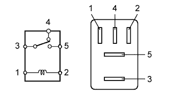
Measure the resistance of the relay.
- Standard resistance:
Tester Connection
Specified Condition
3 - 4
Below 1 Ω
3 - 5
10 kΩ or higher
3 - 4
10 kΩ or higher
(when battery voltage is applied to terminals 1 and 2)
3 - 5
Below 1 Ω
(when battery voltage is applied to terminals 1 and 2)
|
|
||||
| OK | |
|
| 7. CHECK WIRE HARNESS (ENGINE ROOM NO. 1 RELAY BLOCK - SKID CONTROL ECU AND BATTERY) |
Remove the stop light control relay.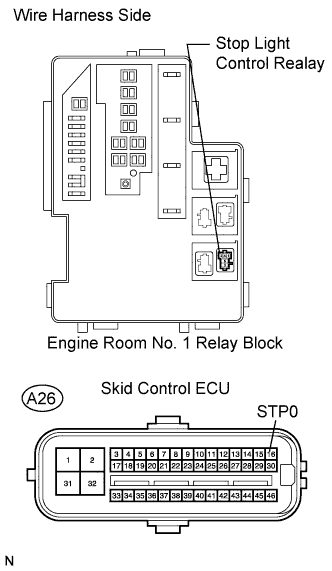
Disconnect the A26 ECU connector.
Measure the voltage of the wire harness side connector.
- Standard voltage:
Tester Connection
Condition
Specified Condition
BRK relay terminal 5 - Body ground
Always
8 to 16 V
BRK relay terminal 2 - Body ground
Ignition switch on (IG)
8 to 16 V
Measure the resistance of the wire harness side connector.
- Standard resistance:
Tester Connection
Specified Condition
BRK relay terminal 1 - A26-16 (STPO)
Below 1 Ω
|
|
||||
| OK | |
|
| 8. RECONFIRM DTC |
Clear the DTC (Click here).
Start the engine.
Drive the vehicle at a speed of 5 km/h (3 mph) or more for several seconds.
Check if the same DTC is output (Click here).
Result Result
Proceed to
DTC is output
A
DTC is not output
B
|
|
||||
| A | ||
|
||
| ||
| 9. CHECK WIRE HARNESS (STOP LIGHT SWITCH - BATTERY) |
Disconnect the A5 switch connector.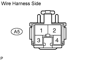
Measure the voltage of the wire harness side connector.
- Standard voltage:
Tester Connection
Specified Condition
A5-2 - Body ground
10 to 14 V
|
|
||||
| OK | |
|
| 10. INSPECT STOP LIGHT SWITCH ASSEMBLY |
Remove the stop light switch connector.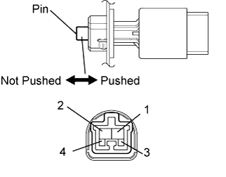
Measure the resistance of the switch.
- Standard resistance:
Tester Connection
Switch Condition
Specified Condition
1 - 2
Switch pin not pushed
Below 1 Ω
1 - 2
Switch pin pushed
10 kΩ or higher
3 - 4
Switch pin not pushed
10 kΩ or higher
3 - 4
Switch pin pushed
Below 1 Ω
|
|
||||
| OK | |
|
| 11. CHECK WIRE HARNESS (STOP LIGHT SWITCH - STOP LIGHT CONTROL RELAY) |
Disconnect the A5 switch connector.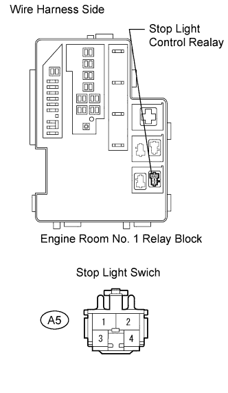
Remove the stop light control relay.
Measure the resistance of the wire harness side connectors.
- Standard resistance:
Tester Connection
Specified Condition
A5-1 - BKR relay Terminal 4
Below 1 Ω
A5-1 - Body ground
10 kΩ or higher
|
|
||||
| OK | |
|
| 12. INSPECT STOP LIGHT CONTROL RELAY (Marking: BRK) |
Remove the stop light control relay from the engine room No. 1 relay block.
Measure the resistance of the relay.
- Standard resistance:
Tester Connection
Specified Condition
3 - 4
Below 1 Ω
3 - 5
10 kΩ or higher
3 - 4
10 kΩ or higher
(when battery voltage is applied to terminals 1 and 2)
3 - 5
Below 1 Ω
(when battery voltage is applied to terminals 1 and 2)
|
|
||||
| OK | |
|
| 13. CHECK WIRE HARNESS (STOP LIGHT AND REAR COMBINATION LIGHT - CONTROL RELAY) |
Disconnect the S1, K13 and K15 light connectors.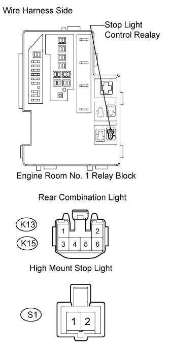
Remove the stop light control relay.
Measure the resistance of the wire harness side connectors.
- Standard resistance:
Tester Connection
Specified Condition
K13-4 - BKR relay terminal 3
Below 1 Ω
K13-4 - Body ground
10 kΩ or higher
K13-1 - Body ground
Below 1 Ω
K15-4 - BKR relay terminal 3
Below 1 Ω
K15-4 - Body ground
10 kΩ or higher
K15-1 - Body ground
Below 1 Ω
S1-2 - BKR relay terminal 3
Below 1 Ω
S1-2 - Body ground
10 kΩ or higher
S1-1 - Body ground
Below 1 Ω
|
|
||||
| OK | ||
|
||
| ||