INSTALLATION
Removal / installation · Vehicles built from Aug 2007
| 1. INSPECT TORQUE CONVERTER CLUTCH ASSEMBLY |

Inspect the torque converter clutch (Click here).
| 2. INSTALL TORQUE CONVERTER CLUTCH ASSEMBLY |
Install the torque converter clutch to the automatic transaxle.
Using a vernier caliper, measure dimension A between the transaxle and end surface of the drive plate.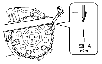

Using a vernier caliper and straightedge, measure dimension B shown in the illustration and check that B is greater than A.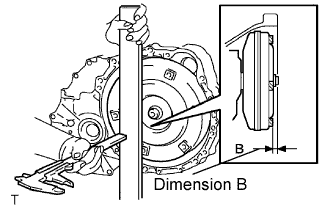
- Standard dimension:
- A + 1.0 mm (0.039 in.) or more
| 3. INSTALL AUTOMATIC TRANSMISSION CASE PROTECTOR |
Install the protector with the 2 bolts.
- Torque:
- 23 N*m{ 235 kgf*cm , 17 ft.*lbf }
| 4. INSTALL NO. 1 TRANSMISSION CONTROL CABLE BRACKET |
Install the cable bracket with the 2 bolts.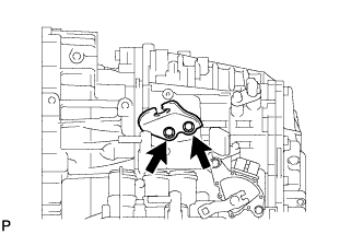
- Torque:
- 12 N*m{ 122 kgf*cm , 9 ft.*lbf }
| 5. INSTALL TRANSMISSION OIL FILLER TUBE SUB-ASSEMBLY |
Install the filler tube with the bolt.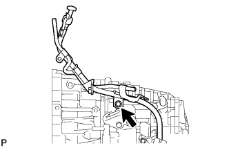
- Torque:
- 5.5 N*m{ 56 kgf*cm , 49 in.*lbf }
Install the ATF dipstick.
| 6. INSTALL AUTOMATIC TRANSAXLE ASSEMBLY |
Install the automatic transaxle to the engine with the 7 upper side mounting bolts.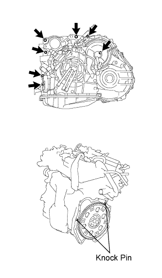
- Torque:
- 64 N*m{ 653 kgf*cm , 47 ft.*lbf }
- NOTICE:
- Make sure that the 2 knock pins are installed on the engine before installing the transaxle.
Install the 3 lower side mounting bolts.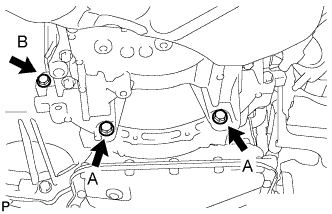
- Torque:
- Bolt A:
- 37 N*m{ 377 kgf*cm , 27 ft.*lbf }
- Bolt B:
- 46 N*m{ 469 kgf*cm , 34 ft.*lbf }
Install the 6 torque converter clutch mounting bolts.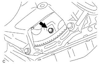
- Torque:
- 41 N*m{ 418 kgf*cm , 30 ft.*lbf }
- HINT:
- First install the black colored bolt and then the other 5 bolts.
Install the flywheel housing under cover with the 2 bolts.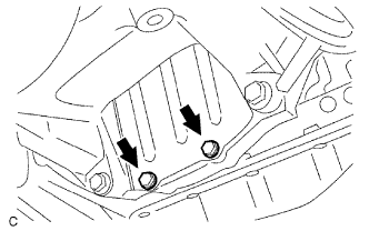
- Torque:
- 7.8 N*m{ 80 kgf*cm , 69 in.*lbf }
| 7. INSTALL TRANSFER ASSEMBLY |
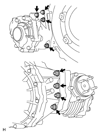 |
Install the transfer to the transaxle with the 6 nuts and 2 bolts.
- Torque:
- 69 N*m{ 700 kgf*cm , 51 ft.*lbf }
| 8. INSTALL ENGINE MOUNTING BRACKET LH |
Install the mounting bracket with the 4 bolts.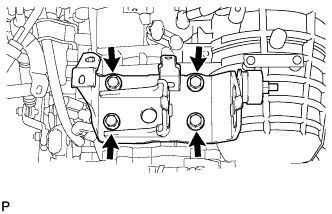
- Torque:
- 64 N*m{ 653 kgf*cm , 47 ft.*lbf }
| 9. INSTALL FRONT ENGINE MOUNTING BRACKET |
Install the mounting bracket with the 4 bolts.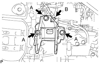
- Torque:
- Bolt A:
- 64 N*m{ 653 kgf*cm , 47 ft.*lbf }
- Bolt B:
- 5.5 N*m{ 56 kgf*cm , 49 in.*lbf }
| 10. INSTALL REAR ENGINE MOUNTING BRACKET |
Install the mounting bracket with the 3 bolts.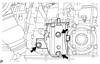
- Torque:
- 45 N*m{ 459 kgf*cm , 33 ft.*lbf }
| 11. CONNECT OIL COOLER INLET HOSE |
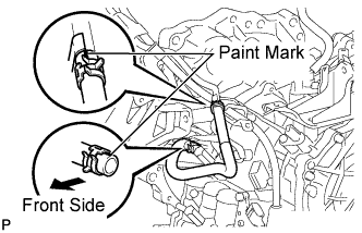 |
Connect the hose to the transaxle and transmission oil filler tube.
| 12. INSTALL OIL COOLER TUBE SUB-ASSEMBLY |
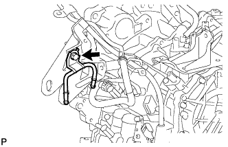 |
Install the tube with the bolt.
- Torque:
- 19 N*m{ 194 kgf*cm , 14 ft.*lbf }
- NOTICE:
- Make sure that the tube rotation stopper contacts the top part of the front engine mounting bracket.
| 13. INSTALL OIL COOLER OUTLET HOSE |
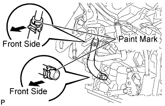 |
Connect the hose to the transaxle and oil cooler tube.
| 14. CONNECT WIRE HARNESS |
Connect the wire harness clamps.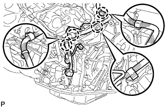
Connect the 2 speed sensor connectors.
Connect the transaxle wire connector.
Connect the park/neutral position switch connector.
| 15. INSTALL STARTER ASSEMBLY |
Install the starter with the 2 bolts.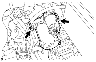
- Torque:
- 37 N*m{ 377 kgf*cm , 27 ft.*lbf }
Connect the starter connector.
Install the terminal nut and close the terminal cap.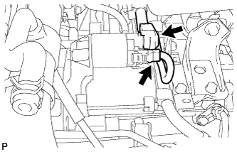
- Torque:
- 9.8 N*m{ 100 kgf*cm , 88 in.*lbf }
| 16. INSTALL ENGINE ASSEMBLY WITH TRANSAXLE |
- HINT:
- (Click here)
| 17. ADD AUTOMATIC TRANSAXLE FLUID |
- Fluid type:
- Toyota Genuine ATF WS
| 18. INSPECT AUTOMATIC TRANSAXLE FLUID |
- HINT:
- Drive the vehicle so that the engine and transaxle are at normal operating temperature.
- Fluid temperature:
- 70 to 80°C (158 to 176°F)
Park the vehicle on a level surface and apply the parking brake.
With the engine idling and the brake pedal depressed, move the shift lever to each position from the P position to the L position, and return it to the P position.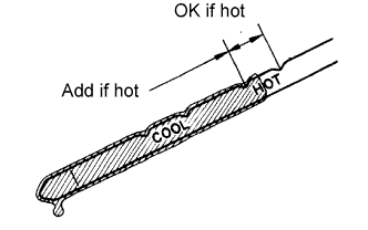
Pull out the dipstick and wipe it clean.
Push it back fully into the pipe.
Pull it out again and check that the fluid level is within the HOT range. If the fluid level is below the HOT range, add new fluid and recheck the fluid level. If the fluid level exceeds the HOT range, drain the fluid once, add a proper amount of new fluid and recheck the fluid level.
| 19. PERFORM RESET MEMORY |
Perform the RESET MEMORY procedures (A/T initialization) (Click here).