Intrusion Sensor Cancel Switch Circuit
Circuit diagnosis · Vehicles built from Nov 2005
DESCRIPTION
When the intrusion sensor cancel switch on the overhead junction block is pressed, the sensor off signal is sent to the theft warning ECU, which causes the intrusion sensor to stop operating.WIRING DIAGRAM
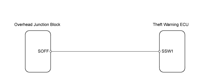

INSPECTION PROCEDURE
| 1. CHECK WIRE HARNESS (INTRUSION SENSOR - THEFT WARNING ECU) |

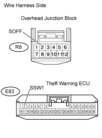 |
Disconnect the R8 junction block connector.
Disconnect the E83 ECU connector.
Measure the resistance of the wire harness side connectors.
- Standard resistance:
Tester Connection
Specified Condition
E83-2 (SSW1) - R8-2 (SOFF)
Below 1 Ω
E83-2 (SSW1) or R8-2 (SOFF) - Body ground
10 kΩ or higher
|
|
||||

| OK | |
 |
| 2. CHECK OVERHEAD JUNCTION BLOCK (OPERATION) |
Temporarily replace the overhead junction block (intrusion sensor) with a new or normally functioning one.
Turn the intrusion sensor off by pressing the intrusion sensor cancel switch. Check if the switch operates normally by checking that the theft deterrent system does not operate when you move your hand in front of the sensor.
- OK:
- Intrusion sensor cancel switch operates normally.
|
|
||||
| OK | ||
 |
||
| ||