Ignition Switch Circuit
Circuit diagnosis · Vehicles built from Nov 2005
DESCRIPTION
When the ignition switch is on (IG), the battery positive voltage is applied to terminal IG of the theft warning ECU. When the battery positive voltage is applied to terminal IG of the ECU while the theft deterrent system is operating, the warning siren stops. Furthermore, the power supplied from terminal IG of the ECU is used as the power for the door courtesy light switch and position switch, etc.WIRING DIAGRAM
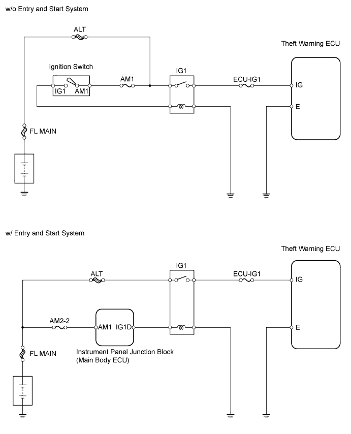

INSPECTION PROCEDURE
| 1. CHECK VEHICLE TYPE |

| Vehicle Type |
Proceed to |
| w/ Entry and start system |
A |
| w/o Entry and start system |
B |
|
|
||||

| A | |
 |
| 2. CHECK BASIC FUNCTION (ENTRY AND START SYSTEM) |
Check that the basic function of the entry and start system (for starting) operates normally (Click here).
- OK:
- Basic function of entry and start system (for starting) operates normally.
|
|
||||

| OK | |
|
| 3. INSPECT FUSE (ECU-IG1, AM1, AM2-2) |
Remove the ECU-IG1 and AM1*1 fuses from the instrument panel junction block.
Remove the AM2-2*2 fuse from the engine room No. 1 relay block.
Measure the resistance of the fuses.
- HINT:
- *1: w/ Entry and start system
- *2: w/o Entry and start system
- Standard resistance:
- Below 1 Ω
|
|
||||
| 4 | |
|
| 4. CHECK WIRE HARNESS (THEFT WARNING ECU - IG POWER SOURCE AND BODY GROUND) |
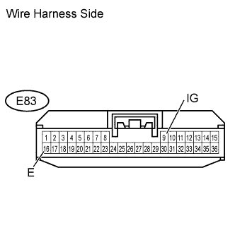 |
Disconnect the E83 ECU connector.
Measure the resistance and voltage of the wire harness side connector.
- Standard resistance:
Tester Connection
Specified Condition
E83-16 (E) - Body ground
Below 1 Ω
- Standard voltage:
Tester Connection
Condition
Specified Condition
E83-9 (IG) - Body ground
Ignition switch off
Below 1 V
Ignition switch on (IG)
10 to 14 V
|
|
||||
| OK | ||
 |
||
| ||