DIAGNOSIS DISPLAY DETAILED DESCRIPTION
Troubleshooting · Vehicles built from Nov 2005
- HINT:
- This section contains a detailed description of displays within diagnostic mode.
- Illustrations may differ from the actual vehicle depending on the device settings and options. Therefore, some detailed areas may not be exactly the same as on the actual vehicle.
- This section contains a detailed description of displays within diagnostic mode.
| DISPLAY CHECK |
Vehicle Signal Check Mode Screen
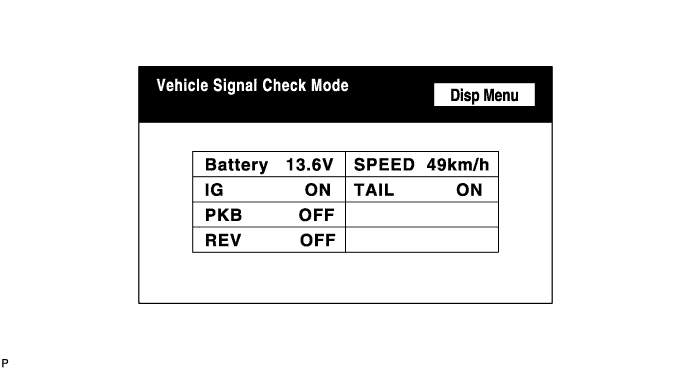

Screen description Name
Contents
Battery
Battery voltage is displayed.
PKB
Parking brake ON / OFF state is displayed.
REV
Reverse signal ON / OFF state is displayed.
IG
IG switch ON / OFF state is displayed.
TAIL
TAIL signal (Light control switch) ON / OFF state is displayed.
SPEED
Vehicle speed is displayed in km/h.
- HINT:
- Only items sending a vehicle signal will be displayed.
- This screen is updated once per second when input signals to the vehicle are changed.
- Only items sending a vehicle signal will be displayed.
Microphone & Voice Recognition Check Screen
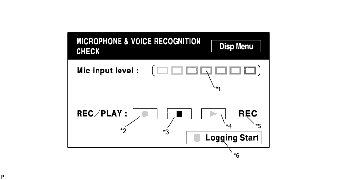
Screen description Name
Contents
Microphone input level meter /*1
The input level of the microphone is sampled every 100 msec., and the result is displayed on an 8 level scale.
Recording switch /*2
Starts recording.
Stop switch /*3
Stops recording.
Play switch /*4
Plays back recorded audio.
Recording indicator /*5
Illuminates when recording.
Voice recording logging start switch /*6
This function is available only for HDD equipped vehicles.
- HINT:
- From when this screen is entered to when this screen is exited, the microphone input function is ON.
- When recording or playing back audio, switches other than the stop switch cannot be pushed.
- If no audio is recorded, the playback switch cannot be pushed.
- Recording stops after 5 seconds have elapsed, or after the stop switch is pushed.
- From when this screen is entered to when this screen is exited, the microphone input function is ON.
CAN Connection Check Screen
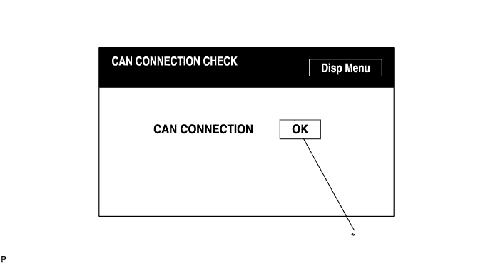
Screen description Display
Contents
CAN Connection check result /*
For CAN connection type systems, display the "CAN CONNECTION CHECK" results. - NG: The ignition switch is on (ACC or IG) and the CAN communication line is malfunctioning or the CAN bus is not connected.
- OK: The ignition switch is on (ACC or IG) and the CAN communication line is normal.
- Blank: The CAN inspection was activated with the ignition switch on (ACC) or off.
- HINT:
- When ignition switch on / off operations, bus malfunctions and bus disconnections occur, the CAN inspection results are updated on the "CAN CONNECTION CHECK" screen in real time.
- NG: The ignition switch is on (ACC or IG) and the CAN communication line is malfunctioning or the CAN bus is not connected.
| NAVIGATION CHECK |
Navigation Check Screen
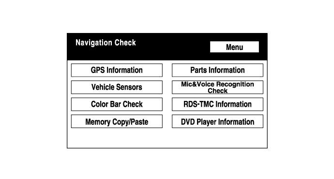
- HINT:
- Each item is grayed out or not displayed based on the device settings.
GPS Information Screen
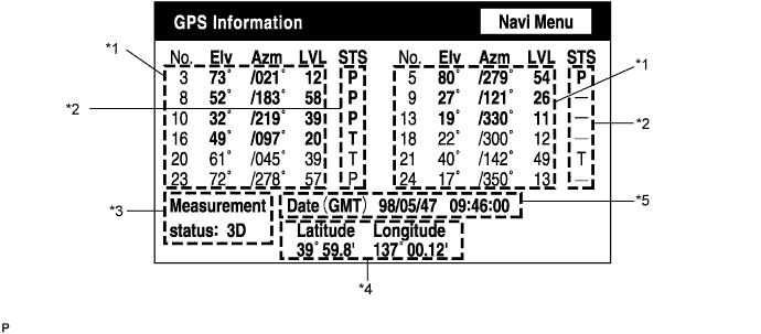
Satellite information/*1
Information from a maximum of 12 satellites is displayed on the screen. This information includes the target GPS satellite number, elevation angle, direction and signal level.Receiving condition/*2
(DENSO model) Display
Contents
T
System is receiving GPS signal, but is not using it for location.
P
System is using GPS signal for location.
-
System cannot receive GPS signal.
(AISIN AW model) Display
Contents
01H
System cannot receive GPS signal.
02H
System is tracing satellite.
03H
System is receiving GPS signal, but is not using it for location.
04H
System is using GPS signal for location.
Position information/*4 Display
Contents
Position
Latitude and longitude information on the current position is displayed.
Position information/*5 Display
Contents
Date
Date / time information obtained from GPS signal is displayed in Greenwich mean time (GMT). Last 4 digits are displayed.
Vehicle Sensor Screen
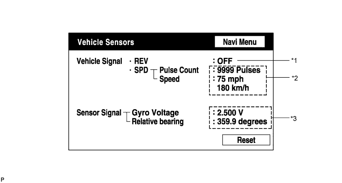
Vehicle signal Display
Contents
REV /*1
REV signal ON / OFF state is displayed.
SPD /*2
SPD signal condition is displayed.
Vehicle signal Display
Contents
Gyro sensor /*3
Gyro sensor output condition is displayed (when vehicle runs straight or is stationary, voltage is approximately 2.5 V).
- HINT:
- Signals are updated once per second only when vehicle sensor signals are changed.
Microphone & Voice Recognition Check Screen
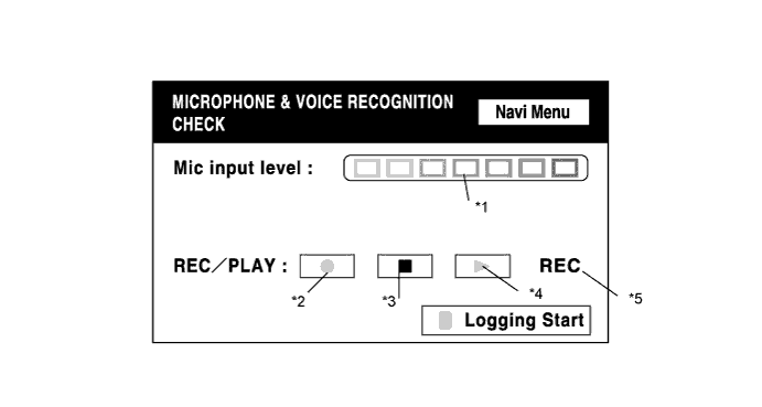
Screen description Name
Contents
Microphone input level meter /*1
The input level of the microphone is sampled every 100 msec., and the result is displayed on an 8 level scale.
Recording switch /*2
Starts recording.
Stop switch /*3
Stops recording.
Play switch /*4
Plays back recorded audio.
Recording indicator /*5
Illuminates when recording.
Voice recording logging start switch /*6
This function is available only for HDD equipped vehicles.
- HINT:
- From when this screen is entered to when this screen is exited, the microphone input function is ON.
- When recording or playing back audio, switches other than the stop switch cannot be pushed.
- If no audio is recorded, the playback switch cannot be pushed.
- Recording stops after 5 seconds have elapsed, or after the stop switch is pushed.
- From when this screen is entered to when this screen is exited, the microphone input function is ON.