INSTALLATION
Removal / installation · Vehicles built from Aug 2007
Versions by build date: Nov 2005 – Dec 2006 Jan 2007 – Jul 2007 from Aug 2007
| 1. INSTALL BRAKE ACTUATOR ASSEMBLY WITH BRACKET |

- NOTICE:
- Do not remove the hole plug before connecting the brake tube. New actuators are filled with brake fluid.
Install the actuator with bracket with the 3 nuts.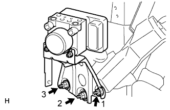

- Torque:
- 19 N*m{ 194 kgf*cm , 14 ft.*lbf }
- HINT:
- The nuts should be tightened in order from 1 to 3 as shown in the illustration.
- NOTICE:
- Be careful not to damage the brake tubes.
Connect the brake tube clamp to the bracket.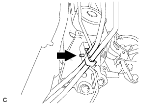
Connect the actuator connector.
| 2. CONNECT BRAKE LINES |
Using SST, connect the 6 brake lines to the correct locations on the actuator, as shown in the illustration.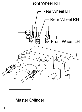
- SST
- 09023-00101
- Torque:
- 15.2 N*m{ 155 kgf*cm , 11 ft.*lbf } without SST
- 14 N*m{ 144 kgf*cm , 10 ft.*lbf } with SST
- HINT:
- Use a torque wrench with a fulcrum length of 30 cm (11.81 in.).
| 3. FILL RESERVOIR WITH BRAKE FLUID |
Set the brake fluid can upside down on the reservoir.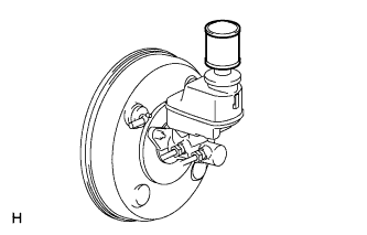
- Fluid:
- SAE J1703 or FMVSS No. 116 DOT3
- NOTICE:
- Make sure there is sufficient brake fluid in the can.
- After adding braking fluid, make sure the reservoir is sufficiently full.
- Make sure there is sufficient brake fluid in the can.
| 4. BLEED AIR FROM BRAKE MASTER CYLINDER |
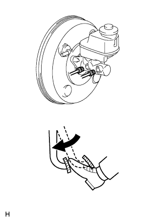 |
- HINT:
- If the master cylinder has been disassembled or if the reservoir becomes empty, bleed air from the master cylinder.
Using SST, disconnect the 2 brake lines from the master cylinder.
- SST
- 09023-00101
Slowly depress and hold the brake pedal.
Block the outer holes with your fingers, and release the pedal.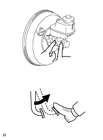
Repeat the 2 previous steps 3 or 4 times.
Using SST, connect the 2 brake lines to the master cylinder.
- SST
- 09023-00101
- Torque:
- 15.2 N*m{ 155 kgf*cm , 11 ft.*lbf } without SST
- 14 N*m{ 144 kgf*cm , 10 ft.*lbf } with SST
- HINT:
- Use a torque wrench with a fulcrum length of 30 cm (11.81 in.).
| 5. BLEED AIR FROM BRAKE LINE |
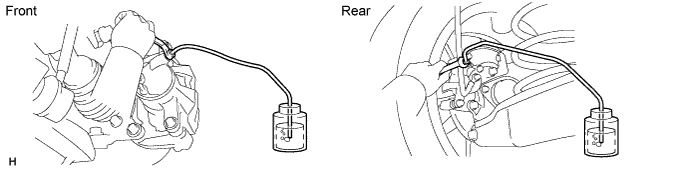
Remove the bleeder plug cap.
Connect the vinyl tube to the bleeder plugs.
Depress the brake pedal several times, and then loosen the bleeder plug with the pedal depressed.
When fluid stops coming out, immediately tighten the bleeder plug. Then release the pedal.
Repeat the 2 previous steps until all the air in the brake fluid is gone.
Tighten the bleeder plug.
- Torque:
- 8.3 N*m{ 85 kgf*cm , 73 in.*lbf }
Install the cap.
Bleed air from the brake line for each wheel by repeating the above procedures.
| 6. BLEED AIR FROM CLUTCH LINE (for Manual Transaxle) |
Fill the brake reservoir with brake fluid and bleed the clutch system.
- Torque:
- 8.3 N*m{ 85 kgf*cm , 74 in.*lbf }
| 7. CHECK BRAKE FLUID LEVEL IN RESERVOIR |
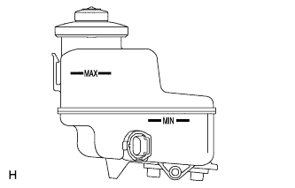 |
Check the fluid level and add fluid if necessary.
- Fluid:
- SAE J1703 or FMVSS No. 116 DOT3
- HINT:
- Add fluid to a level between the reservoir's MIN and MAX lines.
| 8. CHECK FOR BRAKE FLUID LEAKAGE |
| 9. INSTALL AIR CLEANER BRACKET (for 2AD-FHV) |
Install the air cleaner bracket (Click here).
- HINT:
- Refer to the procedures from the installation of the air cleaner bracket up until the installation of the air cleaner cap sub-assembly.
| 10. INSTALL AIR CLEANER BRACKET (for 2AD-FTV) |
Install the air cleaner bracket (Click here).
- HINT:
- Refer to the procedures from the installation of the air cleaner bracket up until the installation of the air cleaner cap sub-assembly.
| 11. INSTALL AIR CLEANER CASE SUB-ASSEMBLY (for 2AZ-FE) |
Install the air cleaner case (Click here).
- HINT:
- Refer to the procedures from the installation of the air cleaner case up until the installation of the purge VSV.
| 12. INSTALL AIR CLEANER CASE SUB-ASSEMBLY (for 1AZ-FE) |
Install the air cleaner case (Click here).
- HINT:
- Refer to the procedures from the installation of the air cleaner case up until the installation of the purge VSV.
| 13. CONNECT CABLE TO NEGATIVE BATTERY TERMINAL |
| 14. CHECK BRAKE ACTUATOR ASSEMBLY WITH INTELLIGENT TESTER |
Check the brake actuator with the intelligent tester (Click here).