Only Driver Door LOCK / UNLOCK Functions do not Operate
Circuit diagnosis · Vehicles built from Nov 2005
DESCRIPTION
The main body ECU receives lock / unlock switch signals and activates the door lock motor accordingly.WIRING DIAGRAM
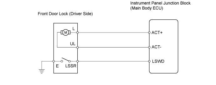

INSPECTION PROCEDURE
| 1. READ VALUE USING INTELLIGENT TESTER (LOCK POSITION SWITCH) |

Use the Data List to check if the door lock is functioning properly.
Main body ECU Item
Measurement Item / Display (Range)
Normal Condition
Diagnostic Note
D-Door Lock Pos SW
Driver side door lock position switch signal ON / OFF
ON: Driver side door is unlocked
OFF: Driver side door is locked
-
- OK:
- When the door lock is operating, the intelligent tester should display as shown in the table.
|
|
||||

| NG | |
 |
| 2. INSPECT FRONT DOOR WITH MOTOR LOCK ASSEMBLY (DRIVER SIDE) |
for LHD: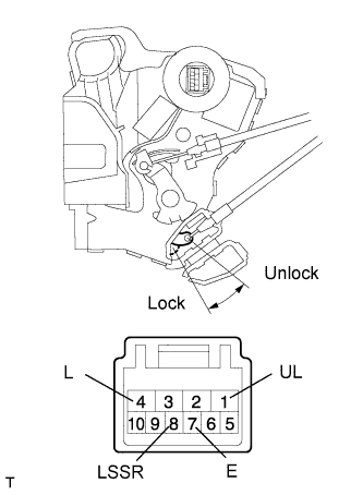
Apply the battery voltage to the motor terminals and check the operation of the door lock motor.
- OK:
Measurement Condition
Specified Condition
Battery positive (+) → 4 (L)
Battery negative (-) → 1 (UL)
Lock
Battery positive (+) → 1 (UL)
Battery negative (-) → 4 (L)
Unlock
Measure the resistance of the position switch.
- Standard resistance:
Tester Connection
Switch Condition
Specified Condition
8 (LSSR) - 7 (E)
Lock
10 kΩ or higher
8 (LSSR) - 7 (E)
Unlock
Below 1 Ω
for RHD (w/o Double Locking System):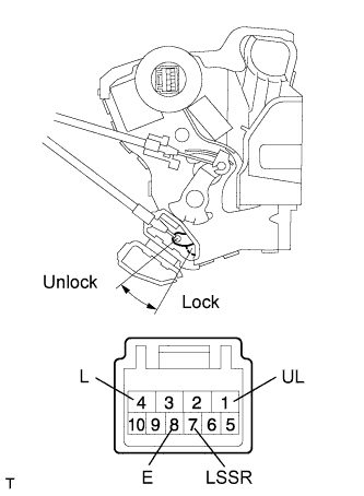
Apply the battery voltage to the motor terminals and check the operation of the door lock motor.
- OK:
Measurement Condition
Specified Condition
Battery positive (+) → 4 (L)
Battery negative (-) → 1 (UL)
Lock
Battery positive (+) → 1 (UL)
Battery negative (-) → 4 (L)
Unlock
Measure the resistance of the position switch.
- Standard resistance:
Tester Connection
Switch Condition
Specified Condition
7 (LSSR) - 8 (E)
Lock
10 kΩ or higher
7 (LSSR) - 8 (E)
Unlock
Below 1 Ω
for RHD (w/ Double Locking System):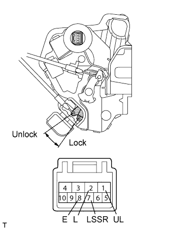
Apply the battery voltage to the motor terminals and check the operation of the door lock motor.
- OK:
Measurement Condition
Specified Condition
Battery positive (+) → 2 (L)
Battery negative (-) → 1 (UL)
Lock
Battery positive (+) → 1 (UL)
Battery negative (-) → 2 (L)
Unlock
Measure the resistance of the position switch.
- Standard resistance:
Tester Connection
Switch Condition
Specified Condition
7 (LSSR) - 8 (E)
Lock
10 kΩ or higher
7 (LSSR) - 8 (E)
Unlock
Below 1 Ω
|
|
||||
| OK | |
|
| 3. CHECK WIRE HARNESS (DOOR LOCK - ECU) |
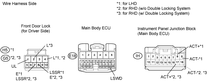
for LHD:
Disconnect the H5 door lock connector.
Disconnect the E18 ECU connector.
Disconnect the IH junction block connector.
Measure the resistance of the wire harness side connectors.
- Standard resistance:
Tester Connection
Specified Condition
H5-1 (UL) - IH-9 (ACT-)
Below 1 Ω
H5-4 (L) - IH-8 (ACT+)
Below 1 Ω
H5-8 (LSSR) - E18-25 (LSWD)
Below 1 Ω
H5-7 (E) - Body ground
Below 1 Ω
for RHD (w/o Double Locking System):
Disconnect the G5 door lock connector.
Disconnect the E18 ECU connector.
Disconnect the IH junction block connector.
Measure the resistance of the wire harness side connectors.
- Standard resistance:
Tester Connection
Specified Condition
G5-1 (UL) - IH-18 (ACT-)
Below 1 Ω
G5-4 (L) - IH-17 (ACT+)
Below 1 Ω
G5-7 (LSSR) - E18-25 (LSWD)
Below 1 Ω
G5-8 (E) - Body ground
Below 1 Ω
for RHD (w/ Double Locking System):
Disconnect the G5 door lock connector.
Disconnect the E18 ECU connector.
Disconnect the IH junction block connector.
Measure the resistance of the wire harness side connectors.
- Standard resistance:
Tester Connection
Specified Condition
G5-1 (UL) - IH-18 (ACT-)
Below 1 Ω
G5-2 (L) - IH-17 (ACT+)
Below 1 Ω
G5-7 (LSSR) - E18-25 (LSWD)
Below 1 Ω
G5-8 (E) - Body ground
Below 1 Ω
|
|
||||
| OK | ||
 |
||
| ||