INSTALLATION
Removal / installation · Vehicles built Aug 2007 – Jul 2008
Versions by build date: Nov 2005 – Dec 2006 Jan 2007 – Jul 2007 Aug 2007 – Jul 2008 from Aug 2008
- HINT:
- Use the same procedures for the LH side and RH side.
- The procedures listed below are for the LH side.
| 1.
INSTALL SKID CONTROL SENSOR LH |
 |
Clean the contacting surface of the axle hub and speed sensor.
- NOTICE:
- Make sure the sensor rotor is clean.
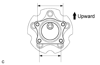
- Place the speed sensor on the axle hub so that the connector position is as high as possible when the axle hub is installed to the vehicle.
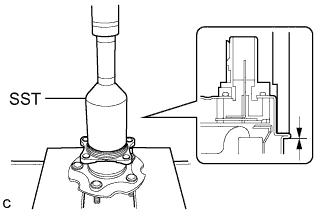
- Using SST and a press, press in the speed sensor to the hub and bearing.
- SST
- 09214-76011
- NOTICE:
- Do not tap the speed sensor directly with a hammer.
- Check that the speed sensor detection part is clean.
- Press in the speed sensor straight and slowly.
| 2.
INSTALL REAR AXLE HUB AND BEARING ASSEMBLY LH |
|
Install the rear axle hub and bearing LH (Click here).
| 3.
INSTALL REAR DISC
|
|
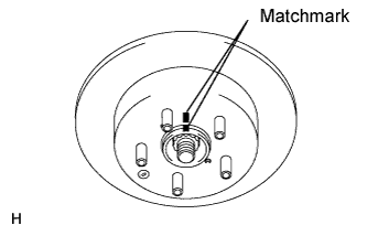
- Align the matchmarks and install the disc.
- HINT:
- When replacing the disc with a new one, select the installation position where the disc has the smallest runout.
| 4.
INSTALL REAR DISC BRAKE CYLINDER MOUNTING LH
|
|
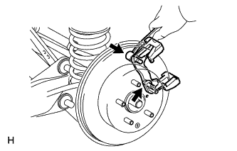
- Install the cylinder mounting with the 2 bolts.
-
Torque:
- 88 N*m{
897 kgf*cm
, 65 ft.*lbf
}
| 5.
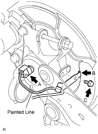
INSTALL SKID CONTROL SENSOR WIRE |
|
- NOTICE:
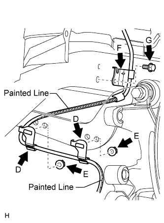
- To prevent interference with other parts, do not twist the sensor wire's painted line areas when installing it.
- Connect the skid control sensor wire connector (labeled A) to the speed sensor.
Install the sensor clamp (labeled B) with the bolt (labeled C).
-
Torque:
- 8.5 N*m{
87 kgf*cm
, 75 in.*lbf
}
- NOTICE:
- Do not twist the sensor wire when installing the clamp.
- Install the sensor clamps (labeled D) with the 2 nuts (labeled E).
-
Torque:
- 5.0 N*m{
51 kgf*cm
, 44 in.*lbf
}
- NOTICE:
- Do not twist the sensor wire when installing the clamps.
Install the sensor clamp (labeled F) with the bolt (labeled G).
-
Torque:
- 8.5 N*m{
87 kgf*cm
, 75 in.*lbf
}
- NOTICE:
- Do not twist the sensor wire when installing the clamp.
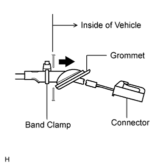
- Insert the connector and grommet to the inside of the vehicle through the passage hole in the wheel house.
- NOTICE:
- Make sure the grommet's band clamp remains on the outside of the vehicle.
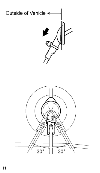
- Hold the grommet and pull it from the inside of the vehicle to the outside of the vehicle. Then fix it in place so that it is not tilted.
- NOTICE:
- When pulling out the grommet, do not grip the sensor wire.
- Fix the grommet in place within the range shown in the illustration.
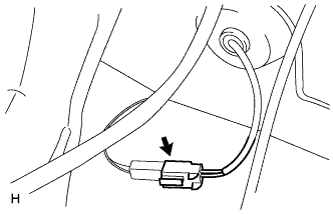
- Connect the skid control sensor wire connector.
| 6.
INSTALL DECK TRIM SIDE PANEL ASSEMBLY LH |
|
Install the deck trim side panel LH (Click here).
- HINT:
- Refer to the procedures from the installation of the deck trim side panel LH up until the installation of the rear door scuff plate LH.
| 7.
INSTALL REAR WHEEL |
|
-
Torque:
- 103 N*m{
1,050 kgf*cm
, 76 ft.*lbf
}
| 8.
CONNECT CABLE TO NEGATIVE BATTERY TERMINAL |
|
| 9.
CHECK SPEED SENSOR SIGNAL |
|
w/o VSC:
Check the speed sensor signal (Click here).
w/ VSC:
Check the speed sensor signal (Click here).