Headlight Beam Level Control Actuator Circuit
Circuit diagnosis · Vehicles built from Nov 2005
DESCRIPTION
The headlight beam level control actuators are activated by operating the headlight leveling switch, allowing the headlight beam angle to be adjusted.WIRING DIAGRAM
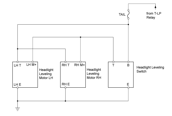

INSPECTION PROCEDURE
| 1. CHECK TAILLIGHT |

Check that the taillight comes on when the light control switch is turned on (TAIL).
- OK:
- Taillight comes on.
|
|
||||

| OK | |
 |
| 2. CHECK WIRE HARNESS (BATTERY - JUNCTION BLOCK) |
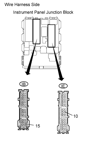 |
Disconnect the IE and IB instrument panel junction block connectors.
Measure the voltage of the wire harness side connectors.
- Standard voltage:
Tester Connection
Condition
Specified Condition
IE-10 - Body ground
Light control switch TAIL
10 to 14 V
IB-15 - Body ground
Light control switch TAIL
10 to 14 V
|
|
||||
| OK | |
|
| 3. CHECK WIRE HARNESS (INSTRUMENT PANEL JUNCTION BLOCK - HEADLIGHT LEVELING SWITCH) |
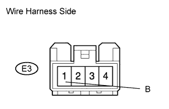 |
Disconnect the E3 headlight leveling switch connector.
Measure the voltage of the wire harness side connector.
- Standard voltage:
Tester Connection
Condition
Specified Condition
E3-1 (B) - Body ground
Light control switch TAIL
10 to 14 V
|
|
||||
| OK | |
|
| 4. INSPECT HEADLIGHT LEVELING SWITCH |
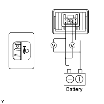 |
Remove the headlight leveling switch.
Connect the positive (+) battery lead to terminal 1 and the negative (-) battery lead to terminal 4.
Check the ratio which is obtained by diving the voltage between terminals 2 and 4 by the voltage between 1 and 4. The voltages must be measured using a voltmeter.
- Standard ratio:
Tester Connection
Switch Position
Specified Condition
1 (+B) - 4 (E) and 2 (T) - 4 (E)
0
0.87 to 0.93
1 (+B) - 4 (E) and 2 (T) - 4 (E)
1
0.76 to 0.82
1 (+B) - 4 (E) and 2 (T) - 4 (E)
2
0.66 to 0.72
1 (+B) - 4 (E) and 2 (T) - 4 (E)
3
0.55 to 0.61
1 (+B) - 4 (E) and 2 (T) - 4 (E)
4
0.44 to 0.50
1 (+B) - 4 (E) and 2 (T) - 4 (E)
5
0.34 to 0.40
|
|
||||
| OK | |
|
| 5. CHECK WIRE HARNESS (LEVELING SWITCH - LEVELING MOTOR AND BODY GROUND) |
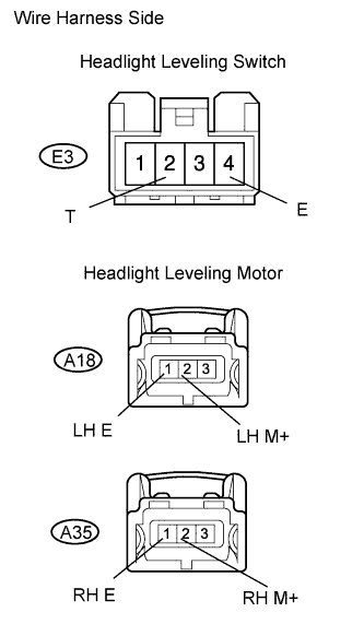 |
Disconnect the E3 headlight leveling switch connector.
Disconnect the A18 and A35 headlight leveling motor connectors.
Measure the resistance of the wire harness side connectors.
- Standard resistance:
Tester Connection
Specified Condition
E3-2 (T) - A18-2 (LH M+)
Below 1 Ω
E3-2 (T) or A18-2 (LH M+) - Body ground
10 kΩ or higher
E3-2 (T) - A35-2 (RH M+)
Below 1 Ω
E3-2 (T) or A35-2 (RH M+) - Body ground
10 kΩ or higher
E3-4 (E) - Body ground
Below 1 Ω
A18-1 (LH E) - Body ground
Below 1 Ω
A35-1 (RH E) - Body ground
Below 1 Ω
|
|
||||
| OK | |
|
| 6. CHECK WIRE HARNESS (JUNCTION BLOCK - LEVELING MOTOR) |
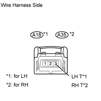 |
Disconnect the A18 and A35 headlight leveling motor connectors.
Measure the voltage of the wire harness side connector.
- Standard voltage:
Tester Connection
Condition
Specified Condition
A18-3 (LH T) - Body ground
Light control switch TAIL
10 to 14 V
A35-3 (RH T) - Body ground
Light control switch TAIL
10 to 14 V
|
|
||||
| OK | ||
 |
||
| ||