Taillight Relay Circuit
Circuit diagnosis · Vehicles built from Nov 2005
DESCRIPTION
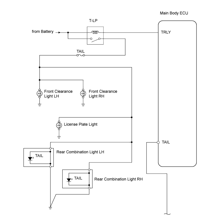
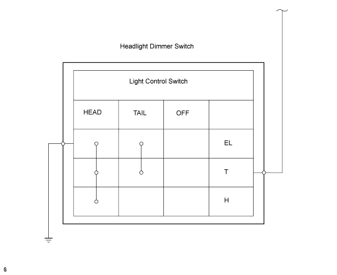
When the light control switch, located on the headlight dimmer switch, is turned to the TAIL position, the taillight relay (marking: T-LP) turns on to illuminate the front clearance lights, rear taillights and license plate light.WIRING DIAGRAM

INSPECTION PROCEDURE
| 1. CHECK WHETHER LIGHTS ILLUMINATE |

Check whether the following lights illuminate: front clearance lights, rear taillights, license plate light.
- Result:
Result
Proceed to
All lights do not illuminate
A
Front clearance lights do not illuminate
B
Rear taillights do not illuminate
C
License plate light does not illuminate
D
All lights illuminate
E
|
|
||||
|
|
||||
|
|
||||
|
|
||||


| A | |
 |
| 2. INSPECT FUSE (TAIL) |
Remove the TAIL fuse from the instrument panel junction block.
Measure the resistance of the fuse.
- Standard resistance:
- Below 1 Ω
|
|
||||
| OK | |
|
| 3. CHECK WIRE HARNESS (INSTRUMENT PANEL JUNCTION BLOCK - BATTERY) |
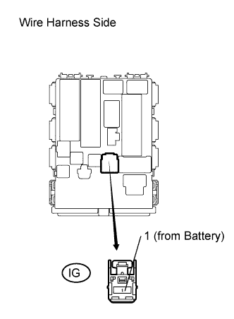 |
Disconnect the IG instrument panel junction block connector.
Measure the voltage of the wire harness side connector.
- Standard voltage:
Tester Connection
Specified Condition
IG-1 - Body ground
10 to 14 V
|
|
||||
| OK | |
|
| 4. CHECK WIRE HARNESS (MAIN BODY ECU - HEADLIGHT DIMMER SWITCH) |
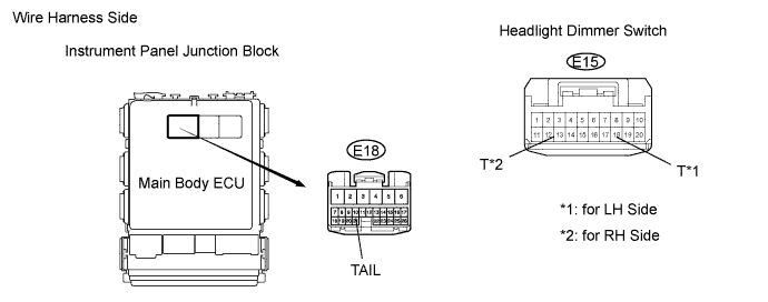
Disconnect the E18 main body ECU connector.
Disconnect the E15 headlight dimmer switch connector.
Measure the resistance of the wire harness side connectors.
- Standard resistance:
for LH side Tester Connection
Specified Condition
E18-21 (TAIL) - E15-18 (T)
Below 1 Ω
for RH side Tester Connection
Specified Condition
E18-21 (TAIL) - E15-13 (T)
Below 1 Ω
|
|
||||
| OK | |
|
| 5. CHECK WIRE HARNESS (HEADLIGHT DIMMER SWITCH - BATTERY) |
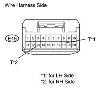 |
Connect the E18 main body ECU connector.
Disconnect the E15 headlight dimmer switch connector.
Measure the voltage of the wire harness side connector.
- Standard voltage:
for LH side Tester Connection
Specified Condition
E15-18 (T) - Body ground
10 to 14 V
for RH side Tester Connection
Specified Condition
E15-13 (T) - Body ground
10 to 14 V
|
|
||||
| OK | |
|
| 6. CHECK WIRE HARNESS (HEADLIGHT DIMMER SWITCH - BODY GROUND) |
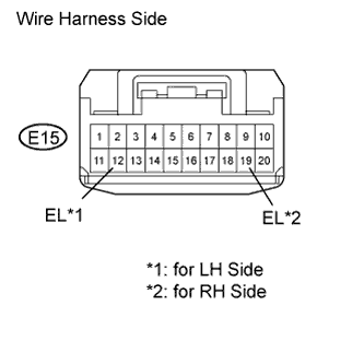 |
Disconnect the E15 headlight dimmer switch connector.
Measure the resistance of the wire harness side connector.
- Standard resistance:
for LH side Tester Connection
Specified Condition
E15-12 (EL) - Body ground
Below 1 Ω
for RH side Tester Connection
Specified Condition
E15-19 (EL) - Body ground
Below 1 Ω
|
|
||||
| OK | |
|
| 7. INSPECT HEADLIGHT DIMMER SWITCH |
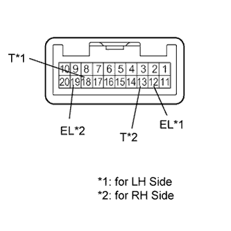 |
Remove the headlight dimmer switch.
Measure the resistance of the switch.
- Standard resistance:
for LH side Tester Connection
Switch Condition
Specified Condition
18 (T) - 12 (EL)
OFF
10 kΩ or higher
18 (T) - 12 (EL)
TAIL
Below 1 Ω
for RH side Tester Connection
Switch Condition
Specified Condition
13 (T) - 19 (EL)
OFF
10 kΩ or higher
13 (T) - 19 (EL)
TAIL
Below 1 Ω
|
|
||||
| OK | ||
 |
||
| ||
| 8. CHECK INSTRUMENT PANEL JUNCTION BLOCK (TAILLIGHT RELAY) |
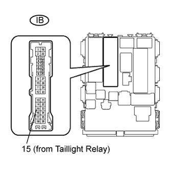 |
Disconnect the IB instrument panel junction block connectors.
Measure the voltage of the junction block.
- Standard voltage:
Tester Connection
Condition
Specified Condition
Junction block IB terminal 15 - Body ground
Light control switch TAIL
10 to 14 V
|
|
||||
| OK | |
|
| 9. CHECK WIRE HARNESS (JUNCTION BLOCK - FRONT CLEARANCE LIGHT AND BODY GROUND) |
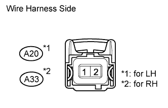 |
Disconnect the A20 and A33 front clearance light connectors.
Measure the voltage and resistance of the wire harness side connectors.
- Standard voltage:
Tester Connection
Condition
Specified Condition
A20-2 - Body ground
Light control switch TAIL
10 to 14 V
A33-2 - Body ground
Light control switch TAIL
10 to 14 V
- Standard resistance:
Tester Connection
Specified Condition
A20-1 - Body ground
Below 1 Ω
A33-1 - Body ground
Below 1 Ω
|
|
||||
| OK | ||
|
||
| ||
| 10. CHECK WIRE HARNESS (MAIN BODY ECU - REAR COMBINATION LIGHT) |
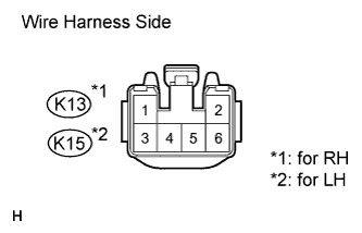 |
Disconnect the K13 and K15 rear combination light connectors.
Measure the voltage and resistance of the wire harness side connectors.
- Standard voltage:
Tester Connection
Condition
Specified Condition
K15-2 - Body ground
Light control switch on (TAIL)
10 to 14 V
K13-2 - Body ground
Light control switch on (TAIL)
10 to 14 V
- Standard resistance:
Tester Connection
Specified Condition
K15-1 - Body ground
Below 1 Ω
K13-1 - Body ground
Below 1 Ω
|
|
||||
| OK | ||
|
||
| ||
| 11. CHECK WIRE HARNESS (MAIN BODY ECU - LICENSE PLATE LIGHT AND BODY GROUND) |
for Short body (w/o Tire Carrier):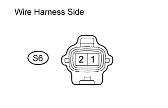
Disconnect the S6 license plate light connector.
Measure the voltage and resistance of the wire harness side connector.
- Standard voltage:
Tester Connection
Condition
Specified Condition
S6-1 - Body ground
Light control switch TAIL
10 to 14 V
- Standard resistance:
Tester Connection
Specified Condition
S6-2 - Body ground
Below 1 Ω
for Short body (w/ Tire Carrier):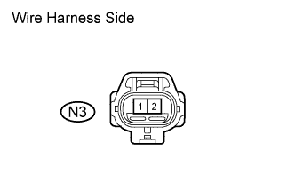
Disconnect the N3 license plate light connector.
Measure the voltage and resistance of the wire harness side connector.
- Standard voltage:
Tester Connection
Condition
Specified Condition
N3-2 - Body ground
Light control switch TAIL
10 to 14 V
- Standard resistance:
Tester Connection
Specified Condition
N3-1 - Body ground
Below 1 Ω
for Long body (w/o Rear fog light):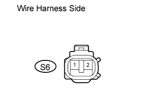
Disconnect the S6 license plate light connector.
Measure the voltage and resistance of the wire harness side connector.
- Standard voltage:
Tester Connection
Condition
Specified Condition
S6-2 - Body ground
Light control switch TAIL
10 to 14 V
- Standard resistance:
Tester Connection
Specified Condition
S6-1 - Body ground
Below 1 Ω
for Long body (w/ Rear fog light):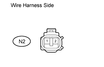
Disconnect the N2 license plate light connector.
Measure the voltage and resistance of the wire harness side connector.
- Standard voltage:
Tester Connection
Condition
Specified Condition
N2-2 - Body ground
Light control switch TAIL
10 to 14 V
- Standard resistance:
Tester Connection
Specified Condition
N2-1 - Body ground
Below 1 Ω
|
|
||||
| OK | ||
|
||
| ||