Operating Light Control Rheostat does not Change Light Brightness
Circuit diagnosis · Vehicles built from Nov 2005
DESCRIPTION
The combination meter assembly controls the combination meter illumination in accordance with the light control signal from the light control rheostat.WIRING DIAGRAM
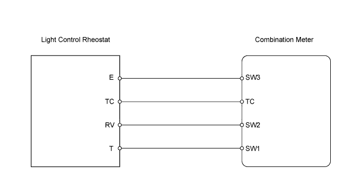

INSPECTION PROCEDURE
| 1. READ VALUE USING DATA LIST (Rheostat value (A/D)) |

Connect the intelligent tester to the DLC3.
Turn the ignition switch on (IG) and the tester ON.
Read the Data List according to the prompts displayed on the tester.
Combination meter Item
Measurement Item / Range (Display)
Normal Condition
Diagnostic Note
Rheostat value (A/D)
Light control rheostat volume / Min.: 0, Max.: 255
Light control rheostat Min. position: 0
Light control rheostat Max. position: 255
-
- OK:
- Light brightness can be changed within the specified range.
|
|
||||

| OK | |
 |
| 2. INSPECT LIGHT CONTROL RHEOSTAT |
Remove the light control rheostat.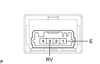
Measure the resistance of the rheostat.
- Standard resistance:
Tester Connection
Rheostat Position
Specified Condition
1 (E) - 3 (RV)
Max.
8 to 12 kΩ
1 (E) - 3 (RV)
Mid.
4.7 kΩ
1 (E) - 3 (RV)
Min.
0 to 50 Ω
|
|
||||
| OK | |
|
| 3. CHECK WIRE HARNESS (COMBINATION METER - LIGHT CONTROL RHEOSTAT) |
Disconnect the E22 meter connector.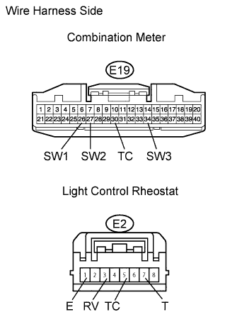
Disconnect the E2 rheostat connector.
Measure the resistance of the wire harness side connectors.
- Standard resistance:
Tester Connection
Specified Condition
E22-26 (SW1) - E2-7 (T)
Below 1 Ω
E22-27 (SW2) - E2-3 (RV)
Below 1 Ω
E22-30 (TC) - E2-5 (TC)
Below 1 Ω
E22-34 (SW3) - E2-1 (E)
Below 1 Ω
E22-26 (SW1) or E2-7 (T) - Body ground
8 to 12 kΩ
E22-27 (SW2) or E2-3 (RV) - Body ground
8 to 12 kΩ (position Max.)
E22-30 (TC) or E2-5 (TC) - Body ground
Below 1 Ω (Tail cancel OFF)
E22-34 (SW3) or E2-1 (E) - Body ground
10 kΩ or higher
|
|
||||
| OK | ||
 |
||
| ||