INSPECTION
Inspection · Vehicles built from Nov 2005
| INSPECT PROPELLER SHAFT WITH CENTER BEARING SHAFT ASSEMBLY |

Using a dial indicator, measure the propeller shaft runout for the front side.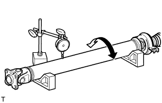

- Maximum runout:
- 0.4 mm (0.02 in.)
- NOTICE:
- Place the dial indicator on the center of the shaft, and perpendicular to the shaft.
Using a dial indicator, measure the propeller shaft runout for the rear side.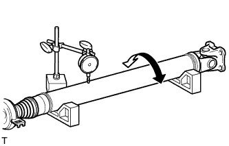
- Maximum runout:
- 0.4 mm (0.02 in.)
- NOTICE:
- Place the dial indicator on the center of the shaft, and perpendicular to the shaft.
| INSPECT JOINT ANGLE |
- NOTICE:
- Perform the measurement with a 4 post lift or pit so that the vehicle is supported by all 4 wheels as if it were on the ground.
Before the angle measurement, stabilize each part by performing procedures like those described below.
Rotate the propeller shaft several times by hand.
Set the jack to the differential, and raise and lower the differential.
Using SST and a straightedge, measure the angle of the transfer flange (angle D) and the angle of the intermediate shaft (angle A).
- SST
- 09370-50010
- NOTICE:
- Make sure the straightedge and SST are at a right angle.
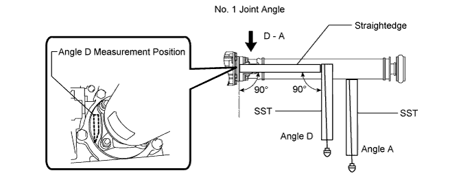
Subtract the measured angle of the intermediate shaft (angle A) from the measured angle of the transfer flange (angle D) to obtain the No. 1 joint angle.
- No. 1 Joint Angle:
Measurement Position
No. 1 Joint Angle
D - A
2°27' +/-60'
Using SST, measure the angle of the intermediate shaft (angle A) and the angle of the propeller shaft (angle B).
- SST
- 09370-50010
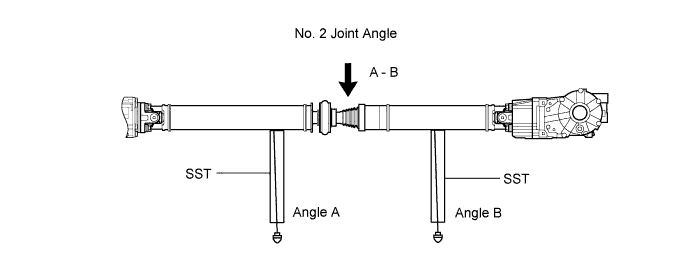
Subtract the measured angle of the propeller shaft (angle B) from the measured angle of the intermediate shaft (angle A) to obtain the No. 2 joint angle.
- No. 2 Joint Angle:
Measurement Position
Engine
Transmission
No. 2 Joint Angle
A - B
1AZ-FE
A/T
1°29' +/-1°30'
M/T
1°28' +/-1°30'
2AZ-FE
A/T
1°35' +/-1°30'
M/T
1°34' +/-1°30'
2GR-FE
A/T
1°35' +/-1°30'
2AD-FTV
2AD-FHV
M/T
1°28' +/-1°30'
Using SST, measure the angle of the propeller shaft (angle B) and the angle of the rear differential (angle C).
- SST
- 09370-50010
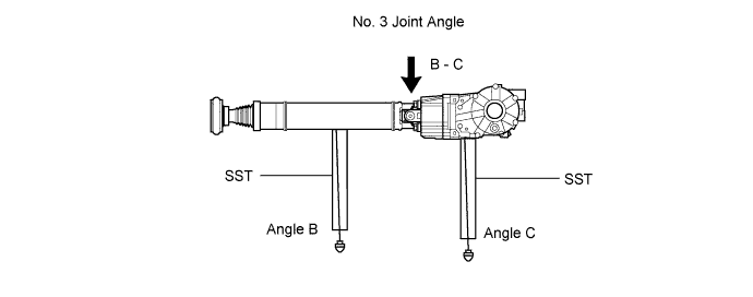
Subtract the measured angle of the propeller shaft (angle B) from the measured angle of the rear differential (angle C) to obtain the No. 3 joint angle.
- No. 3 Joint Angle:
Measurement Position
Engine
Transmission
No. 3 Joint Angle
B - C
1AZ-FE
A/T
2°10' +/-60'
M/T
2°11' +/-60'
2AZ-FE
A/T
2°04' +/-60'
M/T
2GR-FE
A/T
2°04' +/-60'
2AD-FTV
2AD-FHV
M/T
2°10' +/-60'
| ADJUST JOINT ANGLE |
If the measured angle of the propeller shaft is not within the specified range, or there is vibration or noise, use the following procedure to adjust the propeller shaft.
Support the propeller shaft with a jack.
Remove the 2 center bearing mounting bolts.
Slowly lower the jack and disconnect the center bearing.
Select an appropriate adjusting washer thickness from the table below, and obtain a washer set.
- Standard adjusting washer:
Part No.
Thickness
90201-10123
2.0 mm (0.08 in.)
90201-10081
4.5 mm (0.18 in.)
90201-10083
6.5 mm (0.26 in.)
- HINT:
- Use washers of the same thickness on the left and right sides.
- Do not use 2 or more washers stacked together.
- Install the washers.
- Use washers of the same thickness on the left and right sides.