INSTALLATION
Removal / installation · Vehicles built from Nov 2005
| 1. INSTALL DIAPHRAGM OIL SEAL |

Apply a light coat of MP grease No. 2 to the lip of a new diaphragm oil seal.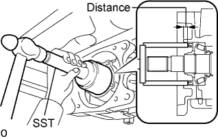

Using SST and a hammer, tap the diaphragm oil seal into the rear differential carrier according to the specification.
- SST
- 09710-30021
(09710-03121)
09950-60010 (09951-00570)
09950-70010 (09951-07100)
- Standard distance:
- 7.0 +-0.5 mm (0.28 +-0.02 in.)
| 2. INSTALL TRANSMISSION COUPLING SHIM |
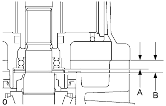 |
Measure each of the dimensions.
- HINT:
- Dimension A: Bearing axis distance
- Dimension B: Drive pinion axis distance
- Dimension A: Bearing axis distance
Select a transmission coupling shim based on the difference between dimensions A and B, and install the shim.
- Transmission coupling shim type:
Difference of dimension A and B mm (in.)
Part No.
Thickness mm (in.)
Identifying Mark
3.96 to 4.01 (0.148 to 0.154)
90564-25024
1.98 to 2.02 (0.078 to 0.080)
1
4.26 to 4.31 (0.161 to 0.168)
90564-25025
2.28 to 2.32 (0.090 to 0.091)
2
4.56 to 4.61 (0.174 to 0.181)
90564-25026
2.58 to 2.62 (0.102 to 0.103)
3
3.81 to 3.86 (0.141 to 0.148)
90564-25027
1.83 to 1.87 (0.072 to 0.074)
4
4.11 to 4.16 (0.154 to 0.161)
90564-25028
2.13 to 2.17 (0.084 to 0.085)
5
4.41 to 4.46 (0.168 to 0.174)
90564-25029
2.43 to 2.47 (0.096 to 0.097)
6
3.71 to 3.76 (0.146 to 0.148)
90564-25031
1.73 to 1.77 (0.068 to 0.70)
8
3.76 to 3.81 (0.148 to 0.150)
90564-25032
1.78 to 1.82 (0.070 to 0.072)
9
3.86 to 3.91 (0.151 to 0.154)
90564-25033
1.88 to 1.92 (0.074 to 0.076)
10
3.91 to 3.96 (0.154 to 0.156)
90564-25034
1.93 to 1.97 (0.076 to 0.078)
11
4.01 to 4.06 (0.158 to 0.160)
90564-25035
2.03 to 2.07 (0.080 to 0.081)
12
4.06 to 4.11 (0.160 to 0.162)
90564-25036
2.08 to 2.12 (0.082 to 0.083)
13
4.16 to 4.21 (0.164 to 0.166)
90564-25037
2.18 to 2.22 (0.086 to 0.087)
14
4.21 to 4.26 (0.166 to 0.168)
90564-25038
2.23 to 2.27 (0.088 to 0.089)
15
4.31 to 4.36 (0.170 to 0.172)
90564-25039
2.33 to 2.37 (0.092 to 0.093)
16
4.36 to 4.41 (0.172 to 0.174)
90564-25040
2.38 to 2.42 (0.094 to 0.095)
17
4.46 to 4.51 (0.176 to 0.178)
90564-25041
2.48 to 2.52 (0.098 to 0.099)
18
4.51 to 4.56 (0.178 to 0.180)
90564-25042
2.53 to 2.57 (0.100 to 0.101)
19
4.61 to 4.66 (0.181 to 0.183)
90564-25043
2.63 to 2.67 (0.104 to 0.105)
20
4.66 to 4.71 (0.183 to 0.185)
90564-25044
2.68 to 2.72 (0.106 to 0.107)
21
| 3. INSTALL TRANSMISSION COUPLING CONICAL SPRING WASHER |
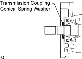 |
Install the transmission coupling conical spring washer to the rear differential carrier.
- NOTICE:
- Install the transmission coupling conical spring washer so that the green marking (protruding part) is facing the front of the vehicle (coupling side).
| 4. INSTALL YOKE |
Using a 5 mm socket hexagon wrench, install the yoke with the 3 bolts.
- Torque:
- 5.0 N*m{ 51 kgf*cm , 44 in.*lbf }
| 5. INSTALL 4WD LINEAR SOLENOID |
Install a new O-ring to the solenoid.
- NOTICE:
- Do not damage or twist the O-ring .
Install the solenoid to the yoke.
Install the snap ring.
| 6. INSTALL ELECTROMAGNETIC COUPLING |
Using white gasoline, remove grease and oil from the alignment surfaces of the rear differential carrier and transmission coupling.
Apply seal packing to the areas indicated in the illustration of the transmission coupling.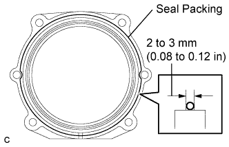
- Seal Packing:
- Toyota Genuine Seal Packing 1281, Three Bond 1281 or equivalent
- NOTICE:
- Apply seal packing in a continuous line 2 to 3 mm (0.08 to 0.12 in.) in diameter.
- Perform the installation with 3 minutes of applying seal packing 1281.
- Apply seal packing in a continuous line 2 to 3 mm (0.08 to 0.12 in.) in diameter.
Install the rear differential carrier cover to the rear differential carrier assembly with the 4 bolts.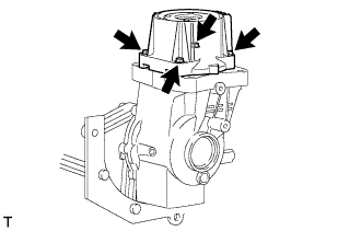
- Torque:
- 19.6 N*m{ 200 kgf*cm , 14 ft.*lbf }
| 7. TEMPORARILY INSTALL PROPELLER WITH CENTER BEARING SHAFT ASSEMBLY |
Align the matchmarks of the transfer and propeller shaft.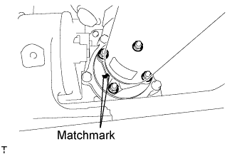
Temporarily install the propeller shaft with center bearing with the 4 nuts and 4 washers.
Align the matchmarks of the differential carrier and propeller shaft.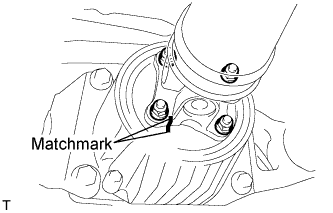
Temporarily install the propeller shaft with center bearing with the 4 bolts and 4 washers.
Temporarily install the center support bearing and center support bearing washer with the 2 bolts.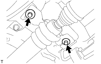
| 8. TIGHTEN PROPELLER WITH CENTER BEARING SHAFT ASSEMBLY |
Tighten the 4 nuts of the propeller shaft and transfer to the torque specification.
- Torque:
- 35 N*m{ 357 kgf*cm , 26 ft.*lbf }
Tighten the 4 nuts of the propeller shaft and differential carrier to the torque specification.
- Torque:
- 35 N*m{ 357 kgf*cm , 26 ft.*lbf }
Check that the center line of the center support bearing housing is perpendicular to the axis of the propeller shaft.
Tighten the 2 bolts of the center support bearing to the torque specification.
- Torque:
- 36.8 N*m{ 375 kgf*cm , 27 ft.*lbf }
| 9. INSPECT AND ADJUST JOINT ANGLE |
- NOTICE:
- Perform the measurement with a 4 post lift or pit so that the vehicle is supported by all 4 wheels as if it were on the ground.
Before the angle measurement, stabilize each part by performing procedures like those described below.
Rotate the propeller shaft several times by hand.
Set the jack to the differential, and raise and lower the differential.
Using SST and a straightedge, measure the angle of the transfer flange (angle D) and the angle of the intermediate shaft (angle A).
- SST
- 09370-50010
- NOTICE:
- Make sure the straightedge and SST are at a right angle.
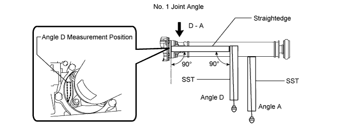
Subtract the measured angle of the intermediate shaft (angle A) from the measured angle of the transfer flange (angle D) to obtain the No. 1 joint angle.
- No. 1 Joint Angle:
Measurement Position
No. 1 Joint Angle
D - A
2°27' +/-60'
Using SST, measure the angle of the intermediate shaft (angle A) and the angle of the propeller shaft (angle B).
- SST
- 09370-50010
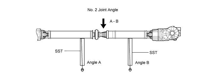
Subtract the measured angle of the propeller shaft (angle B) from the measured angle of the intermediate shaft (angle A) to obtain the No. 2 joint angle.
- No. 2 Joint Angle:
Measurement Position
Engine
Transmission
No. 2 Joint Angle
A - B
1AZ-FE
A/T
1°29' +/-1°30'
M/T
1°28' +/-1°30'
2AZ-FE
A/T
1°35' +/-1°30'
M/T
1°34' +/-1°30'
2GR-FE
A/T
1°35' +/-1°30'
2AD-FTV
2AD-FHV
M/T
1°28' +/-1°30'
Using SST, measure the angle of the propeller shaft (angle B) and the angle of the rear differential (angle C).
- SST
- 09370-50010
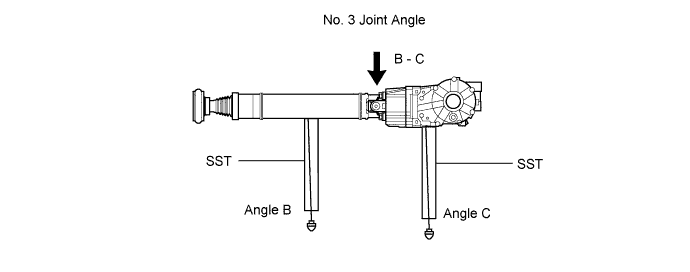
Subtract the measured angle of the propeller shaft (angle B) from the measured angle of the rear differential (angle C) to obtain the No. 3 joint angle.
- No. 3 Joint Angle:
Measurement Position
Engine
Transmission
No. 3 Joint Angle
B - C
1AZ-FE
A/T
2°10' +/-60'
M/T
2°11' +/-60'
2AZ-FE
A/T
2°04' +/-60'
M/T
2GR-FE
A/T
2°04' +/-60'
2AD-FTV
2AD-FHV
M/T
2°10' +/-60'
| 10. ADD DIFFERENTIAL OIL |
Stop the vehicle on a level surface.
Using a 10 mm socket hexagon wrench, remove the rear differential filler plug and gasket.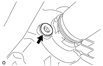
Check that the oil level is between 0 to 5 mm (0 to 0.20 in.) from the bottom lip of the differential filler plug hole.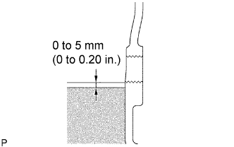
- NOTICE:
- After changing the oil seal, drive the vehicle and then check the oil level again.
- Too much or too little oil will lead to differential problems.
- After changing the oil seal, drive the vehicle and then check the oil level again.
- If there is not enough oil, inspect for oil leaks, and fill the differential carrier assembly with hypoid gear oil.
- Recommended viscosity:
- SAE 90
- Standard oil grade:
- Hypoid gear oil SX API GL-5
- Standard differential oil capacity:
- 0.45 to 0.55 liters (0.48 to 0.58 US qts., 0.40 to 0.48 Imp. qts.)
Using a 10 mm socket hexagon wrench, install a new gasket and the rear differential filler plug.
- Torque:
- 39 N*m{ 398 kgf*cm , 29 ft.*lbf }
| 11. CHECK FOR DIFFERENTIAL OIL LEAKAGE |
- If gas is leaking, tighten the areas necessary to stop the leak. Replace damaged parts as necessary.