ADJUSTMENT
Removal / installation · Vehicles built from Aug 2007
Versions by build date: Nov 2005 – Jul 2007 from Aug 2007
| 1. INSPECT TIRE |

Inspect the tire (Click here).
| 2. MEASURE VEHICLE HEIGHT |
Measure the vehicle height (Click here).
| 3. INSPECT TOE-IN |
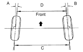  |
- Standard toe-in:
Item
Specified Condition
Toe-in
(total)
A + B: 0°11' +-10' (0.18° +-0.17°)
C - D: 2.3 +-1 mm (0.09 +-0.04 in.)
- If the toe-in is not within the specified range, inspect the suspension parts and replace them if necessary.
| 4. ADJUST TOE-IN |
Measure the length of the left and right rear No. 1 suspension arms.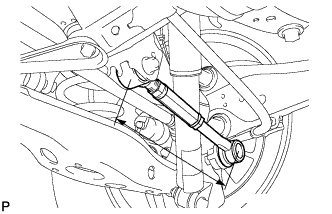
- Standard difference:
- 1.0 mm (0.0394 in.) or less
Loosen the 2 lock nuts of the adjusting tube.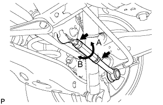
- HINT:
- Loosen the 2 lock nuts of the adjusting tube on the other side using the same procedure.
If the difference between the length of the left and right rear No. 1 suspension arms is not within the specification, adjust the value to within the specification using the method below.
If the toe-in value deviates towards the inside, turn the adjusting tube of the shorter No. 1 suspension arm assembly in the direction which increases arm length until the difference between the left and right suspension arms is within the specification.
If the toe-in value deviates towards the outside, turn the adjusting tube of the longer No. 1 suspension arm assembly in the direction which decreases arm length until the difference between the left and right suspension arms is within the specification.
Measure the toe-in again.
Turn the left and right adjusting tubes in the same direction by the same amount to adjust the toe-in.
- Adjustment Value:
- 2.3 +-1.0 mm (0.0905 +-0.0394 in.)
- HINT:
- When the adjusting tube of the rear No. 1 suspension arm assembly LH is turned one revolution in the direction of A in the illustration, the toe-in changes to the inside by approximately 3.7 mm (0.146 in.)
- When the adjusting tube of the rear No. 1 suspension arm assembly LH is turned one revolution in the direction of B in the illustration, the toe-in changes to the outside by approximately 3.7 mm (0.146 in.).
- When the adjusting tube of the rear No. 1 suspension arm assembly LH is turned one revolution in the direction of A in the illustration, the toe-in changes to the inside by approximately 3.7 mm (0.146 in.)
Tighten the lock nuts of the adjusting tube.
- Torque:
- 56 N*m{ 571 kgf*cm , 41 ft.*lbf }
- NOTICE:
- Make sure to hold the adjusting tube at the width across flats when tightening the nuts.
- HINT:
- Tighten the 2 lock nuts of the adjusting tube on the other side using the same procedure.
| 5. INSPECT CAMBER |
Install the camber-caster-kingpin gauge or set the vehicle on the wheel alignment tester.
Inspect the camber.
- Standard camber:
Item
Specified Condition
Camber
Right-left error
*Tire Size: 215/70R16
-0°58' +-45' (-0.97° +-0.75°)
45' (0.75°) or less
Tire Size: 225/65R17
Tire Size: 235/55R18
-1°07' +-45' (-1.12° +-0.75°)
45' (0.75°) or less
Australia
-0°52' +-45' (0.87° +-0.75°)
45' (0.75°) or less
- *: Europe only
- HINT:
- Camber is not adjustable. If the measurement is not within the specified range, inspect the suspension parts for damage and/or wear, and replace them if necessary.