REMOVAL
Removal / installation · Vehicles built Nov 2005 – Dec 2006
Versions by build date: Nov 2005 – Dec 2006 Jan 2007 – Jul 2007 from Aug 2007
- HINT:
- Use the same procedures for the RH side and LH side.
- The procedures listed below are for the LH side.
| 2.
DISCONNECT NO. 2 PARKING BRAKE CABLE ASSEMBLY
|
 |
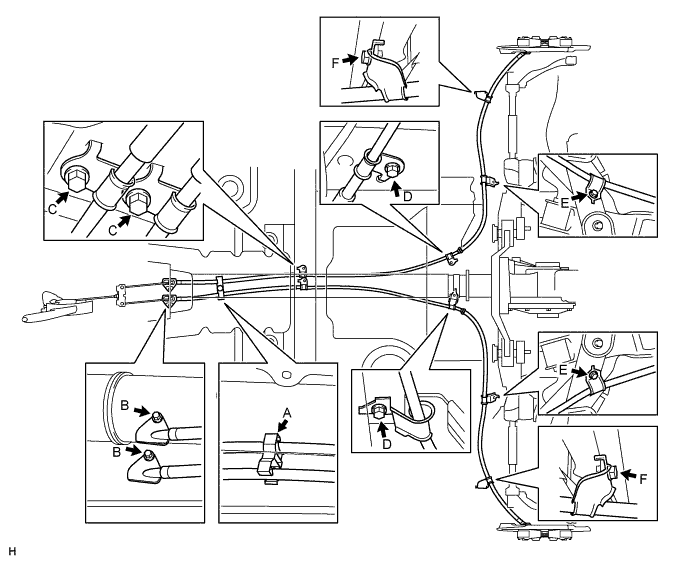

Remove the cable clamp (labeled A) from the body.
Remove the casing cap bolt (labeled B) from the body.
Remove the clamp bolt (labeled C) from the body.
Remove the clamp bolt (labeled D) from the crossmember.
Remove the clamp bolt (labeled E) from the rear suspension crossmember.
Remove the clamp bolt (labeled F) from the trailing arm.
Disconnect the cable from the parking brake shoe lever and backing plate.
Disconnect the cable from the lever (Click here).
Remove the bolt and disconnect the cable from the backing plate.
| 3.
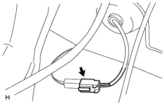
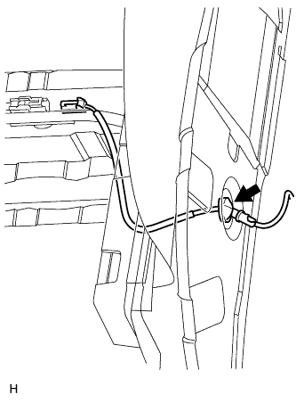
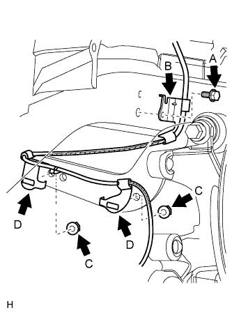
DISCONNECT SKID CONTROL SENSOR WIRE (for 2WD)
|
|
- Disconnect the skid control sensor wire connector.
- Disconnect the grommet of the skid control sensor wire from the hole of the wheel house.
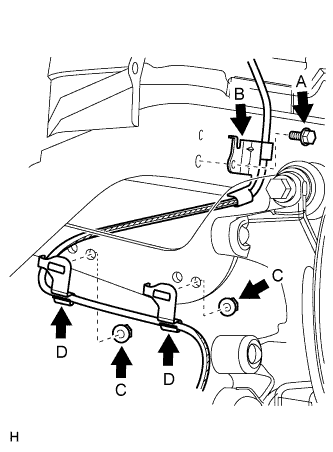
- Remove the bolt (labeled A) and sensor clamp (labeled B) from the side member.
Remove the 2 nuts (labeled C) and sensor clamps (labeled D) from the upper arm.
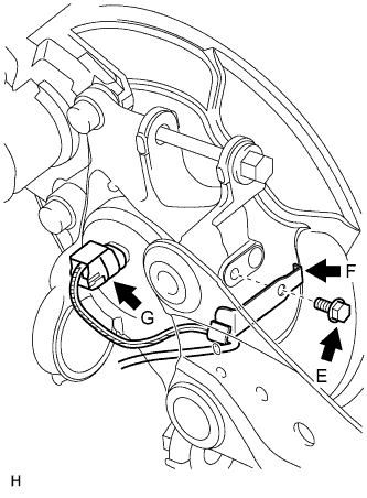
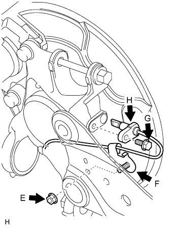
- Remove the bolt (labeled E) and sensor clamp (labeled F) from the carrier.
Disconnect the skid control sensor wire connector (labeled G) from the speed sensor.
| 4.
DISCONNECT REAR SPEED SENSOR LH (for 4WD)
|
|
- Disconnect the speed sensor connector.
- Disconnect the grommet of the speed sensor wire from the hole of the wheel house.
- Remove the bolt (labeled A) and sensor clamp (labeled B) from the side member.
Remove the 2 nuts (labeled C) and sensor clamps (labeled D) from the upper arm.
- Remove the nut (labeled E) and sensor clamp (labeled F) from the trailing arm.
Remove the bolt (labeled G) and sensor body (labeled H) from the carrier.
- NOTICE:
- Keep the sensor tip and sensor installation hole free from foreign matter.
| 5.
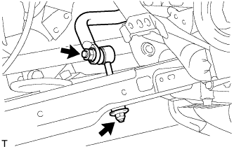
REMOVE REAR STABILIZER LINK ASSEMBLY LH
|
|
- Remove the nut and disconnect the link from the suspension No. 2 arm.
Remove the nut and link from the stabilizer bar.
| 6.
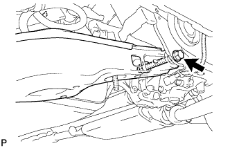
DISCONNECT REAR NO. 2 SUSPENSION ARM ASSEMBLY LH |
|
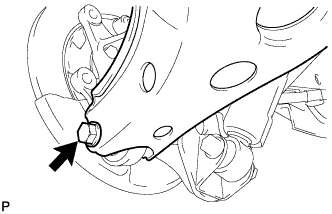
Loosen the bolt from the suspension member side.
- NOTICE:
- Do not remove the bolt and nut. Only loosen them.
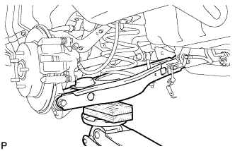
- Support the No. 2 suspension arm LH with a jack.
- NOTICE:
- Place a wooden or rubber block between the jack and the arm.
- Remove the bolt and nut from the axle carrier side.
Slowly lower the jack, and disconnect the No. 2 suspension arm from the axle carrier.
| 7.
REMOVE REAR COIL SPRING INSULATOR UPPER LH
|
|
Remove the insulator upper from the coil spring.
| 8.
REMOVE REAR COIL SPRING LH
|
|
Remove the coil spring from the suspension No. 2 arm.
| 9.
REMOVE REAR COIL SPRING INSULATOR LOWER LH
|
|
Remove the insulator lower from the suspension No. 2 arm.
| 10.
REMOVE REAR NO. 2 SUSPENSION ARM ASSEMBLY LH |
|
Remove the bolt, nut and suspension arm from the suspension member.