ON-VEHICLE INSPECTION
Inspection · Vehicles built from Aug 2007
| INSPECT INTAKE AIR CONTROL VALVE ASSEMBLY |

Inspection procedure when using the intelligent tester.
Warm up the engine.
Stop the engine.
Connect the intelligent tester to the DLC3.
Turn the ignition switch to the ON position.
Turn the tester on.
Select the following menu items: Powertrain / Engine and ECT / Active Test / Activate the VSV for Intake Control.
Make sure that a clicking sound is heard from the intake air control valve when current flows. If the result is not as specified, replace the intake air surge tank.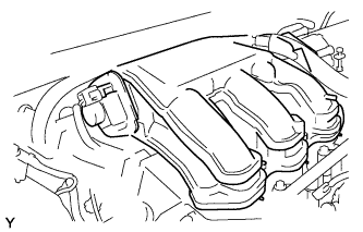

Inspection procedure when applying voltage between the terminals.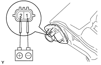
Disconnect the connector from the intake air control valve.
Apply battery voltage between terminals 1 (-) and 2 (+) of the intake air control valve. Check that a clicking sound is heard from the intake air control valve.
If the result is not as specified, replace the intake air surge tank.
| INSPECT VACUUM SWITCHING VALVE |
Perform the Active Test to operate the VSV (Click here).
| INSPECT AIR CLEANER ASSEMBLY |
Inspect the actuator.
Apply 80 kPa (600 mmHg, 23.6 in. Hg) of vacuum to the actuator. Check if the valve rotates open, as shown in the illustration.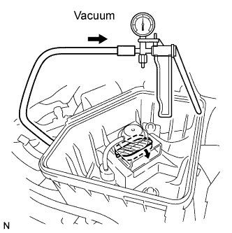
Apply vacuum for 1 minute. The actuator should continue to keep the valve open.
If the result is not as specified, replace the air cleaner case assembly.
Inspect the vacuum tank.
Connect the vacuum pump to port A.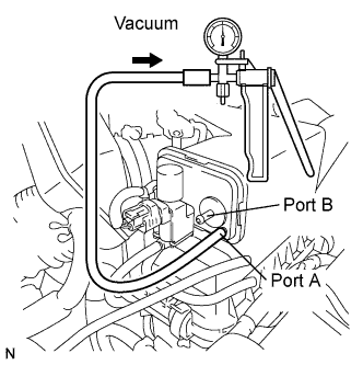
Apply a vacuum of 66.7 kPa (500 mmHg, 20 in. Hg) to the vacuum tank.
Apply vacuum for 1 minute, and then check that the pressure does not change.
Check that there is no ventilation when pressure is applied to port B, and that there is ventilation when a vacuum is applied to port B.
If the result is not as specified, replace the air cleaner cap assembly.
| INSPECT VACUUM SWITCHING VALVE |
Check the resistance of the VSV.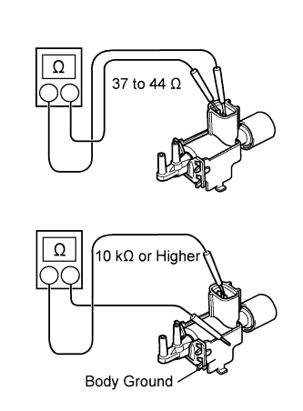
- Standard resistance:
Tester Connection
Specified Condition
1 - 2
37 to 44 Ω at 20°C (68°F)
1 - Body ground
2 - Body ground
10 kΩ or higher
Check VSV operation.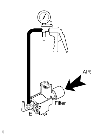
When vacuum is applied to the E port, check that air is sucked into the filter.
If the result is not as specified, replace the VSV.
Apply battery voltage across the terminals. When vacuum is applied to the F port, check that air is sucked into the E port.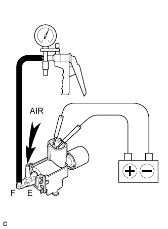
If the result is not as specified, replace the VSV.