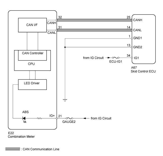
VEHICLE STABILITY CONTROL SYSTEM > ABS Warning Light Remains ON |
| 1.CHECK CAN COMMUNICATION SYSTEM |
Check if a CAN communication system DTC is output (Click here).
| Result | Proceed to |
| DTC is not output. | A |
| DTC is output. | B |
|
| ||||
| A | |
 |
| 2.INSPECT SKID CONTROL ECU CONNECTOR |
Check if the skid control ECU connector is properly installed.
|
| ||||
| OK | |
|
| 3.CHECK HARNESS AND CONNECTOR (SKID CONTROL ECU - BATTERY AND BODY GROUND) |
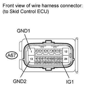 |
Disconnect the skid control ECU connector.
Measure the resistance according to the value(s) in the table below.
| Tester Connection | Condition | Specified Condition |
| A67-1 (GND1) - Body ground | Always | Below 1 Ω |
| A67-13 (GND2) - Body ground | Always | Below 1 Ω |
Measure the voltage according to the value(s) in the table below.
| Tester Connection | Switch Condition | Specified Condition |
| A67-34 (IG1) - Body ground | Ignition switch ON | 11 to 14 V |
|
| ||||
| OK | |
|
| 4.PERFORM ACTIVE TEST USING INTELLIGENT TESTER (ABS WARNING LIGHT) |
Connect the intelligent tester to the DLC3.
Start the engine.
Select the Active Test mode on the intelligent tester (Click here).
| Tester Display | Test Part | Control Range | Diagnostic Note |
| ABS Warning Light | ABS warning light | Warning light ON / OFF | Observe the combination meter. |
|
| ||||
| OK | ||
 | ||
| ||
