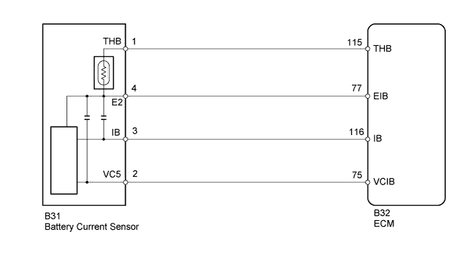
DTC P0516 Battery Temperature Sensor Circuit Low |
DTC P0517 Battery Temperature Sensor Circuit High |
| DTC Detection Drive Pattern | DTC Detection Condition | Trouble Area |
| Ignition switch ON for 1 second | Battery current sensor output value is 0.2 V or less for 0.5 seconds or more with the ignition switch ON (1 trip detection logic) |
|
| DTC Detection Drive Pattern | DTC Detection Condition | Trouble Area |
| Ignition switch ON for 1 second | Battery current sensor output value is 4.8 V or higher for 0.5 seconds or more with the ignition switch ON (1 trip detection logic) |
|
| 1.INSPECT BATTERY CURRENT SENSOR |
 |
Disconnect the battery current sensor connector.
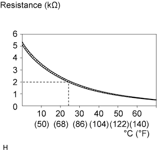
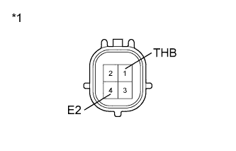
Measure the resistance according to the value(s) in the table below.
| Tester Connection | Condition | Specified Condition |
| 1 (THB) - 4 (E2) | 20 to 30°C (68 to 86°F) | 1.5 to 2.5 kΩ |
| *1 | Component without harness connected (Battery Current Sensor) |
Reconnect the battery current sensor connector.
|
| ||||
| OK | |
 |
| 2.CHECK WIRE HARNESS (BATTERY CURRENT SENSOR - ECM) |
 |
Disconnect the battery current sensor connector.
Disconnect the ECM connector.
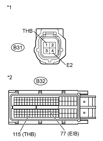
Measure the resistance according to the value(s) in the table below.
| Tester Connection | Condition | Specified Condition |
| B31-1 (THB) - B32-115 (THB) | Always | Below 1 Ω |
| B31-4 (E2) - B32-77 (EIB) | Always | Below 1 Ω |
| Tester Connection | Condition | Specified Condition |
| B31-1 (THB) or B32-115 (THB) - Body ground | Always | 10 kΩ or higher |
| B31-4 (E2) or B32-77 (EIB) - Body ground | Always | 10 kΩ or higher |
| *1 | Front view of wire harness connector (to Battery Current Sensor) |
| *2 | Front view of wire harness connector (to ECM) |
Reconnect the battery current sensor connector.
Reconnect the ECM connector.
|
| ||||
| OK | |
|
| 3.REPLACE ECM |
Replace the ECM (Click here).
|
| ||||
| 4.REPLACE BATTERY CURRENT SENSOR |
Replace the battery current sensor (Click here).
|
| ||||
| 5.REPAIR OR REPLACE HARNESS OR CONNECTOR |
Repair or replace the harness or connector.
| NEXT | |
|
| 6.CONFIRM WHETHER MALFUNCTION HAS BEEN SUCCESSFULLY REPAIRED |
Connect the intelligent tester to the DLC3.
Clear the DTCs (Click here).
Turn the ignition switch to ON for 1 second or more.
Enter the following menus: Powertrain / Engine and ECT / DTC.
Confirm that the DTC is not output again.
| NEXT | ||
 | ||
| ||
