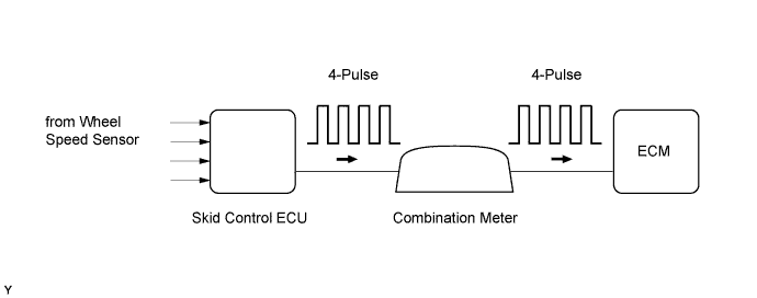
DTC P0500 Vehicle Speed Sensor "A" |
| DTC Detection Drive Pattern | DTC Detection Condition | Trouble Area |
| Drive the vehicle at 10 km/h (6.3 mph) or more | Conditions (a), (b) and (c) are met for 8 seconds or higher (2 trip detection logic): (a) Engine coolant temperature is higher than 70°C (158°F). (b) Injection volume is 19 mm3st or more. (c) No speed signal is input to the ECM. |
|
| Drive the vehicle at 10 km/h (6.3 mph) or more | Conditions (a) and (b) are met for 6 seconds or more (2 trip detection logic): (a) During the fuel-cut operation. (b) No speed signal is input to the ECM. |
| DTC No. | Data List |
| P0500 | Vehicle Speed |
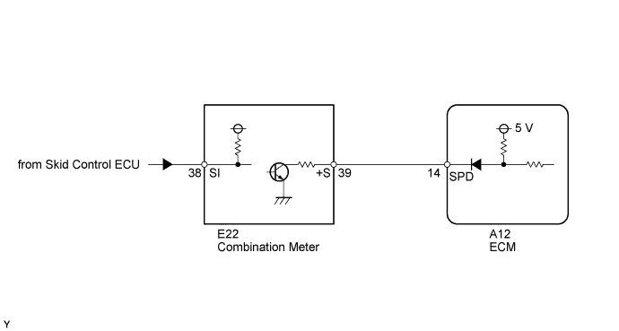
| 1.CHECK OPERATION OF SPEEDOMETER |
Drive the vehicle and check whether the operation of the speedometer in the combination meter is normal.
|
| ||||
| OK | |
 |
| 2.READ VALUE USING INTELLIGENT TESTER (VEHICLE SPEED) |
Connect the intelligent tester to the DLC3.
Turn the ignition switch to ON and start the engine.
Turn the tester on.
Enter the following menus: Powertrain / Engine and ECT / Data List / All Data / Vehicle Speed.
Drive the vehicle.
Read the value displayed on the tester.
|
| ||||
|
| ||||
| 3.CHECK HARNESS AND CONNECTOR |
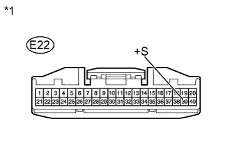 |
Disconnect the combination meter connector.
Measure the voltage according to the value(s) in the table below.
| Tester Connection | Switch Condition | Specified Condition |
| E22-39 (+S) - Body ground | Ignition switch ON | 4.5 to 5.5 V |
| *1 | Front view of wire harness connector (to Combination Meter) |
Reconnect the combination meter connector.
|
| ||||
| OK | |
|
| 4.CHECK COMBINATION METER ASSEMBLY (SPD SIGNAL WAVEFORM) |
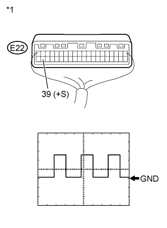 |
Move the shift lever to neutral.
Jack up the vehicle.
Check the voltage between the terminal of the combination meter and the body ground while a wheel is turned slowly.
| Tester Connection | Switch Condition | Specified Condition |
| E22-39 (+S) - Body ground | Ignition switch ON | Voltage generated intermittently |
| *1 | Component without harness connected (Combination Meter) |
| Result | Proceed to |
| OK | A |
| NG | B |
|
| ||||
|
| ||||
| 5.CHECK HARNESS AND CONNECTOR (COMBINATION METER ASSEMBLY - ECM) |
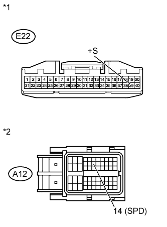 |
Disconnect the combination meter connector.
Disconnect the ECM connector.
Measure the resistance according the value(s) in the table below.
| Tester Connection | Condition | Specified Condition |
| E22-39 (+S) - A12-14 (SPD) | Always | Below 1 Ω |
| Tester Connection | Condition | Specified Condition |
| E22-39 (+S) or A12-14 (SPD) - Body ground | Always | 10 kΩ or higher |
| *1 | Front view of wire harness connector (to Combination Meter) |
| *2 | Front view of wire harness connector (to ECM) |
Reconnect the combination meter connector.
Reconnect the ECM connector.
|
| ||||
| OK | |
|
| 6.REPLACE ECM |
Replace the ECM (Click here).
|
| ||||
| 7.CHECK SPEEDOMETER CIRCUIT |
Check the speedometer circuit (Click here).
|
| ||||
| 8.REPLACE COMBINATION METER ASSEMBLY |
Replace the combination meter (Click here).
|
| ||||
| 9.REPAIR OR REPLACE HARNESS OR CONNECTOR |
Repair or replace the harness or connector.
| NEXT | |
|
| 10.CONFIRM WHETHER MALFUNCTION HAS BEEN SUCCESSFULLY REPAIRED |
Connect the intelligent tester to the DLC3.
Clear the DTCs (Click here).
Turn the ignition switch off.
Start the engine.
Drive the vehicle at 10 km/h (6.3 mph) or more.
Enter the following menus: Powertrain / Engine and ECT / DTC.
Confirm that the pending DTC is not output again.
| NEXT | ||
 | ||
| ||
