RADIO ANTENNA CORD > REMOVAL |
| 1. DISCONNECT CABLE FROM NEGATIVE BATTERY TERMINAL |
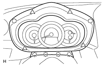
| 2. REMOVE INSTRUMENT CLUSTER FINISH PANEL SUB-ASSEMBLY |
|
Using a screwdriver, detach the 4 clips and 6 claws, and then remove the instrument cluster finish panel.
| 3. REMOVE COMBINATION METER ASSEMBLY |
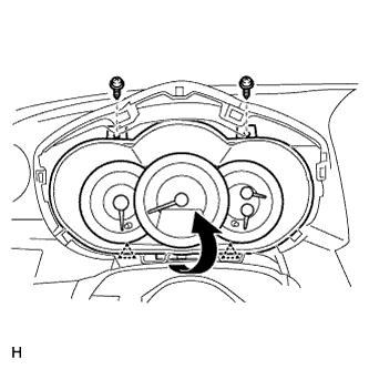 |
Remove the 2 screws.
Pull the combination meter in the direction indicated by the arrow in the illustration to detach the 2 clips.
Disconnect the connector and remove the combination meter.
| 4. REMOVE NO. 2 INSTRUMENT CLUSTER FINISH PANEL CENTER |
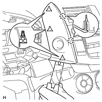 |
Using a moulding remover, detach the 3 clips and 2 claws, and then remove the cluster finish panel.
Disconnect the connector.
| 5. REMOVE NO. 1 INSTRUMENT CLUSTER FINISH PANEL CENTER |
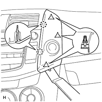 |
Using a moulding remover, detach the 3 clips and 2 claws, and then remove the cluster finish panel.
Disconnect the connector.
| 6. REMOVE RADIO RECEIVER ASSEMBLY WITH BRACKET (w/ Radio Receiver) |
Remove the radio receiver with bracket (Click here).
| 7. REMOVE STEREO OPENING COVER (w/o Radio Receiver) |
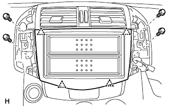 |
Remove the 4 bolts.
Detach the 4 clips and remove the stereo opening cover.
| 8. REMOVE NAVIGATION RECEIVER ASSEMBLY WITH BRACKET (w/ Navigation System) |
for HDD:
Remove the radio receiver with bracket (Click here).
for DVD:
Remove the radio receiver with bracket (Click here).
| 9. REMOVE INSTRUMENT PANEL REGISTER ASSEMBLY CENTER |
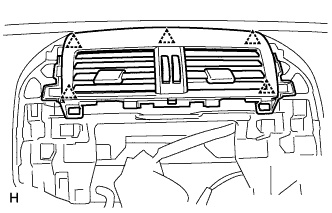 |
Using a moulding remover, detach the 5 clips and remove the instrument panel register.
| 10. REMOVE GLOVE COMPARTMENT DOOR ASSEMBLY |
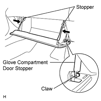 |
Open the glove compartment door.
Detach the claw from the glove compartment door stopper.
While pushing in the sides of the glove compartment door in the direction indicated by the arrows in the illustration, open the door to release it from the 2 stoppers.
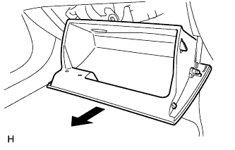 |
Open the door as much as possible.
Pull the glove compartment door toward the rear of the vehicle to detach the 2 hinges and remove the glove compartment door.
| 11. REMOVE FRONT PILLAR GARNISH LH |
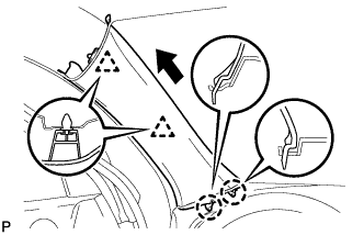 |
w/o Curtain Shield Airbag:
Using a clip remover, detach the 2 clips.
Pull the garnish in the direction indicated by the arrow in the illustration to detach the 2 claws. Then remove the garnish.
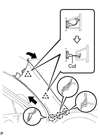 |
w/ Curtain Shield Airbag:
Detach the 2 clips.
Cut off the 2 clips.
Detach the 3 claws and remove the garnish.
Remove the 2 clips from the vehicle body.
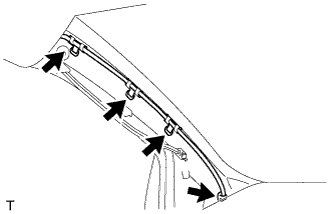 |
Using a clip remover, remove the 4 wiring harness clamps.
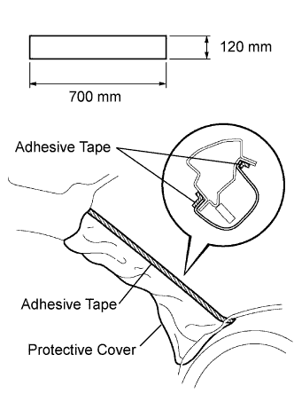 |
w/ Curtain Shield Airbag:
Thoroughly cover the airbag with cloth or nylon of 700 mm (27.56 in.) x 120 mm (4.72 in.) and fix the ends of the cover with adhesive tape, as shown in the illustration.
| 12. REMOVE FRONT PILLAR GARNISH RH |
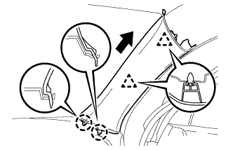 |
w/o Curtain Shield Airbag:
Using a clip remover, detach the 2 clips.
Pull the garnish in the direction indicated by the arrow in the illustration to detach the 2 claws. Then remove the garnish.
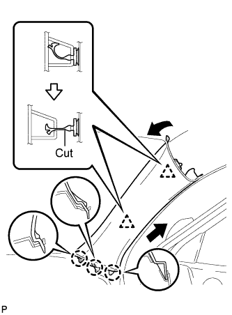 |
w/ Curtain Shield Airbag:
Detach the 2 clips.
Cut off the 2 clips.
Detach the 3 claws and remove the garnish.
Remove the 2 clips from the vehicle body.
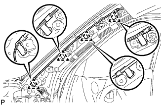 |
Using a clip remover, remove the 4 antenna cord clamps.
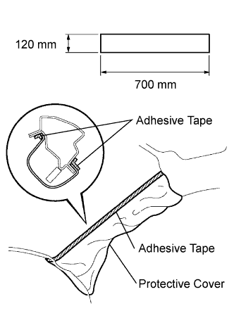 |
w/ Curtain Shield Airbag:
Thoroughly cover the airbag with cloth or nylon of 700 mm (27.56 in.) x 120 mm (4.72 in.) and fix the ends of the cover with adhesive tape, as shown in the illustration.
| 13. REMOVE UPPER INSTRUMENT PANEL |
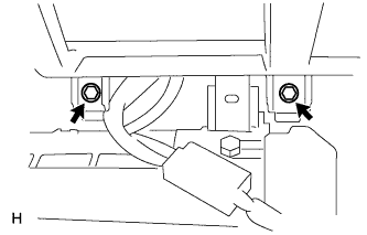 |
Remove the 2 bolts from the passenger airbag.
Disconnect the passenger airbag connector.
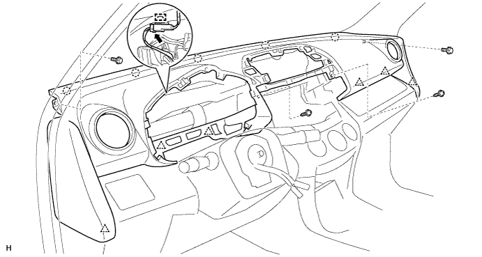
Remove the 2 bolts and 2 screws.
Disconnect the connector and detach the clamp.
Detach the 6 clips and 5 claws and remove the instrument panel.
| 14. REMOVE ANTENNA CORD SUB-ASSEMBLY |
for 2AD-FTV, 2AD-FHV (w/ Radio Receiver):
Disconnect the connector.
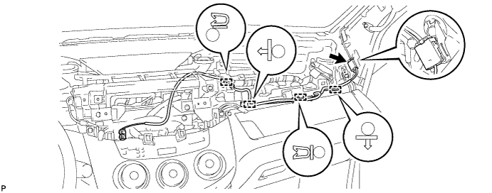
Detach the 4 clamps and remove the antenna cord.
except 2AD-FTV, 2AD-FHV (w/o Radio Receiver):
Disconnect the connector.
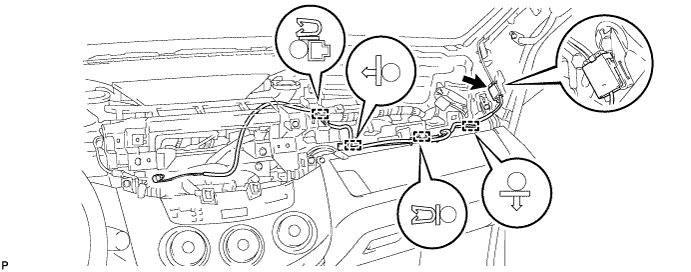
Detach the 4 clamps and remove the antenna cord.
| 15. REMOVE ROOF HEADLINING ASSEMBLY |
for Shot Body:
Remove the roof headlining (Click here).
for Long Body:
Remove the roof headlining (Click here).
| 16. REMOVE NO. 3 ANTENNA CORD SUB-ASSEMBLY |
for Short Body (w/o Sliding Roof):
Apply masking tape to the antenna cord to mark it.
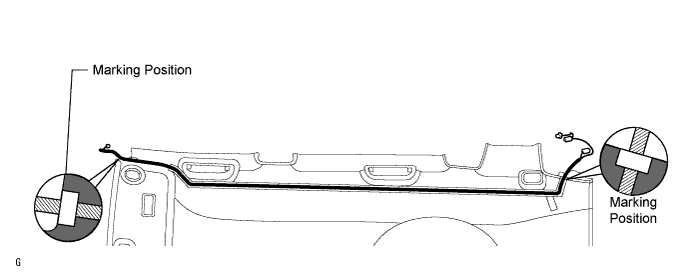
Remove the antenna cord from the roof headlining.
Remove the double-sided tape from the roof headlining.
for Short Body (w/ Sliding Roof):
Apply masking tape to the antenna cord to mark it.
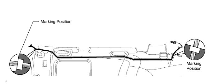
Remove the antenna cord from the roof headlining.
Remove the double-sided tape from the roof headlining.
for Long Body (w/o Sliding Roof):
Apply masking tape to the antenna cord to mark it.
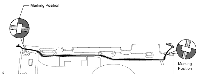
Remove the antenna cord from the roof headlining.
Remove the double-sided tape from the roof headlining.
for Long Body (w/ Sliding Roof):
Apply masking tape to the antenna cord to mark it.
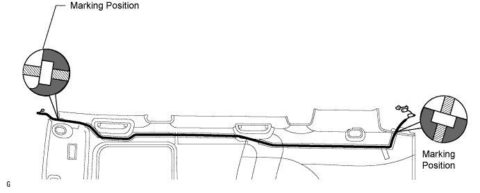
Remove the antenna cord from the roof headlining.
Remove the double-sided tape from the roof headlining.