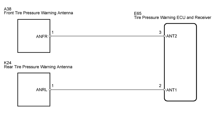
DTC C2195/95 Multi-receiver Antenna Circuit (Test Mode DTC) |
| DTC Code | DTC Detection Condition | Trouble Area |
| C2195/95 | In test mode, tire pressure antenna circuit malfunction occurs |
|
| 1.PERFORM FORCED TRANSMISSION OF TRANSMITTER ID OF ALL WHEELS |
Set the pressure of each tire to the specified value.
Connect the intelligent tester to the DLC3.
Select "ID Tire Inflation Pressure" by following the prompts displayed on the intelligent tester.
| Tester Display | Measurement Item/Range | Normal Condition | Diagnostic Note |
| ID1 Tire Inflation Pressure | ID1 tire inflation pressure/ min.: -100 kPa (-1 kgf/cm2, -14 psi) max.: 537.5 kPa (5.4 kgf/cm2, 78 psi) | Actual tire pressure | If -100 kPa (-1 kgf/cm2, -14 psi) is displayed, the data has not been received.* |
| ID2 Tire Inflation Pressure | ID2 tire inflation pressure/ min.: -100 kPa (-1 kgf/cm2, -14 psi) max.: 537.5 kPa (5.4 kgf/cm2, 78 psi) | Actual tire pressure | If -100 kPa (-1 kgf/cm2, -14 psi) is displayed, the data has not been received.* |
| ID3 Tire Inflation Pressure | ID3 tire inflation pressure/ min.: -100 kPa (-1 kgf/cm2, -14 psi) max.: 537.5 kPa (5.4 kgf/cm2, 78 psi) | Actual tire pressure | If -100 kPa (-1 kgf/cm2, -14 psi) is displayed, the data has not been received.* |
| ID4 Tire Inflation Pressure | ID4 tire inflation pressure/ min.: -100 kPa (-1 kgf/cm2, -14 psi) max.: 537.5 kPa (5.4 kgf/cm2, 78 psi) | Actual tire pressure | If -100 kPa (-1 kgf/cm2, -14 psi) is displayed, the data has not been received.* |
Rapidly release the tire pressure from any tire to 40 kPa (0.4 kgf/cm2, 5.8 psi) / 30seconds or more.
Check the Data List.
| Result | Proceed to |
| All "ID Tire Inflation Pressure" data does not change (front side) | A |
| All "ID Tire Inflation Pressure" data does not change (rear side) | B |
| All "ID Tire Inflation Pressure" data (ID1 to ID4) changes | C |
|
| ||||
|
| ||||
| A | |
 |
| 2.CHECK WIRE HARNESS (ECU - FRONT TIRE PRESSURE WARNING ANTENNA) |
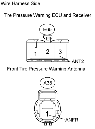 |
Disconnect the E65 ECU connector.
Disconnect the A38 antenna connector.
Measure the resistance of the wire harness side connectors.
| Tester Connection | Specified Condition |
| E65-3 (ANT2) - A38-1 (ANFR) | Below 1 Ω |
|
| ||||
| OK | |
|
| 3.REPLACE FRONT TIRE PRESSURE WARNING ANTENNA |
| NEXT | |
|
| 4.CHECK TEST MODE DTC |
Check test mode DTC (Click here).
|
| ||||
| OK | ||
 | ||
| ||
| 5.CHECK WIRE HARNESS (ECU - REAR TIRE PRESSURE ANTENNA) |
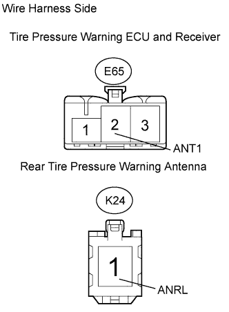 |
Disconnect the E65 ECU connector.
Disconnect the K24 antenna connector.
Measure the resistance of the wire harness side connectors.
| Tester Connection | Specified Condition |
| E65-2 (ANT1) - K24-1 (ANRL) | Below 1 Ω |
|
| ||||
| OK | |
|
| 6.REPLACE REAR TIRE PRESSURE WARNING ANTENNA |
| NEXT | |
|
| 7.CHECK TEST MODE DTC |
Check test mode DTC (Click here).
|
| ||||
| OK | ||
| ||
| ||

