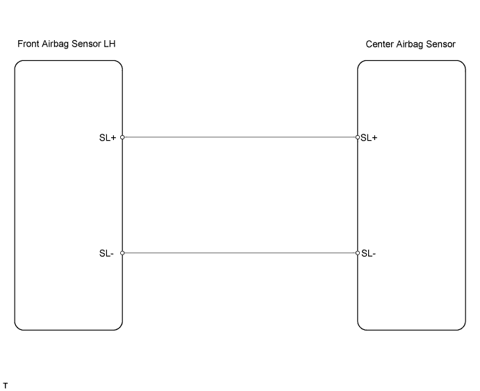
DTC B1607/84 Lost Communication with Front Satellite Sensor Bus LH |
DTC B1608/84 Front Satellite Sensor Bus LH Initialization Incomplete |
DTC B1617/84 Lost Communication with Front Airbag Sensor LH |
DTC B1618/84 Front Airbag Sensor LH Initialization Incomplete |
| DTC No. | DTC Detection Condition | Trouble Area |
| B1607/84 B1608/84 B1618/84 B1618/84 | When one of following conditions is met:
|
|
| 1.CHECK CONNECTION OF CONNECTOR |
Turn the ignition switch off.
Disconnect the cable from the negative (-) battery terminal, and wait for at least 90 seconds.
Check that the connectors are properly connected to the center airbag sensor and the front airbag sensor LH.
|
| ||||
| OK | |
 |
| 2.CHECK FRONT AIRBAG SENSOR LH CIRCUIT (OPEN) |
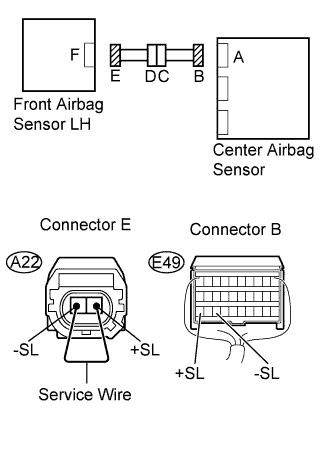 |
Disconnect the connectors from the center airbag sensor and the front airbag sensor LH.
Using a service wire, connect A22-2 (+SL) and A22-1 (-SL) of connector E.
Measure the resistance of the wire harness side connector.
| Tester Connection | Specified Condition |
| E49-30 (+SL) - E49-28 (-SL) | Below 1 Ω |
|
| ||||
| OK | |
|
| 3.CHECK FRONT AIRBAG SENSOR LH CIRCUIT (SHORT) |
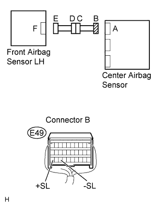 |
Disconnect the service wire from connector E.
Measure the resistance of the wire harness side connector.
| Tester Connection | Specified Condition |
| E49-30 (+SL) - E49-28 (-SL) | 1 MΩ or higher |
|
| ||||
| OK | |
|
| 4.CHECK FRONT AIRBAG SENSOR LH CIRCUIT (TO B+) |
|
Connect the cable to the negative (-) battery terminal, and wait for at least 2 seconds.
Turn the ignition switch on (IG).
Measure the voltage of the wire harness side connector.
| Tester Connection | Specified Condition |
| E49-30 (+SL) - Body ground | Below 1 V |
| E49-28 (-SL) - Body ground | Below 1 V |
|
| ||||
| OK | |
|
| 5.CHECK FRONT AIRBAG SENSOR LH CIRCUIT (TO GROUND) |
|
Turn the ignition switch off.
Disconnect the cable from the negative (-) battery terminal, and wait for at least 90 seconds.
Measure the resistance of the wire harness side connector.
| Tester Connection | Specified Condition |
| E49-30 (+SL) - Body ground | 1 MΩ or higher |
| E49-28 (-SL) - Body ground | 1 MΩ or higher |
|
| ||||
| OK | |
|
| 6.CHECK FRONT AIRBAG SENSOR LH |
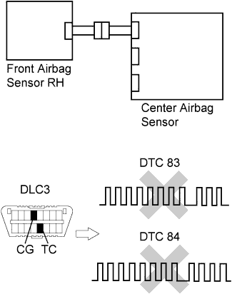 |
Connect the connectors to the center airbag sensor.
Interchange the front airbag sensor RH and LH, and connect the connectors to them.
Connect the cable to the negative (-) battery terminal, and wait for at least 2 seconds.
Turn the ignition switch on (IG), and wait for at least 60 seconds.
Clear the DTCs (Click here).
Turn the ignition switch off.
Turn the ignition switch on (IG), and wait for at least 60 seconds.
Check the DTCs (Click here).
| Result | Proceed to |
| DTC B1602/83, B1603/83, B1612/83, B1613/83, B1607/84, B1608/84, B1617/84 and B1618/84 are not output. | A |
| DTC B1607/84, B1608/84, B1617/84 and B1618/84 are output | B |
| DTC B1602/83, B1603/83, B1612/83 and B1613/83 are output | C |
|
| ||||
|
| ||||
| A | ||
 | ||
| ||
| 7.CHECK ENGINE ROOM MAIN WIRE (OPEN) |
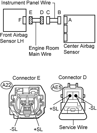 |
Disconnect the service wire from connector E.
Disconnect the engine room main wire connector from the instrument panel wire.
Using a service wire, connect AE5-1 (+SL) and AE5-2 (-SL) of connector D.
Measure the resistance of the wire harness side connector.
| Tester Connection | Specified Condition |
| A22-2 (+SL) - A22-1 (-SL) | Below 1 Ω |
|
| ||||
| OK | ||
| ||
| ||
| 8.CHECK ENGINE ROOM MAIN WIRE (SHORT) |
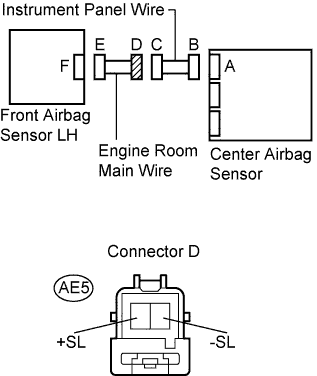 |
Disconnect the engine room main wire connector from the instrument panel wire.
Measure the resistance of the wire harness side connector.
| Tester Connection | Specified Condition |
| AE5-1 (+SL) - AE5-2 (-SL) | 1 MΩ or higher |
|
| ||||
| OK | ||
| ||
| ||
| 9.CHECK ENGINE ROOM MAIN WIRE (TO B+) |
|
Turn the ignition switch off.
Disconnect the cable from the negative (-) battery terminal, and wait for at least 90 seconds.
Disconnect the engine room main wire connector from the instrument panel wire.
Connect the cable to the negative (-) battery terminal, and wait for at least 2 seconds.
Turn the ignition switch on (IG).
Measure the voltage of the wire harness side connector.
| Tester Connection | Specified Condition |
| AE5-1 (+SL) - Body ground | Below 1 V |
| AE5-2 (-SL) - Body ground | Below 1 V |
|
| ||||
| OK | ||
| ||
| ||
| 10.CHECK ENGINE ROOM MAIN WIRE (TO GROUND) |
|
Disconnect the engine room main wire connector from the instrument panel wire.
Measure the resistance of the wire harness side connector.
| Tester Connection | Specified Condition |
| AE5-1 (+SL) - Body ground | 1 MΩ or higher |
| AE5-2 (-SL) - Body ground | 1 MΩ or higher |
|
| ||||
| OK | ||
| ||
| ||

