INTAKE MANIFOLD > REMOVAL |
| 1. REMOVE DIESEL THROTTLE BODY ASSEMBLY |
Remove the diesel throttle body assembly (Click here).
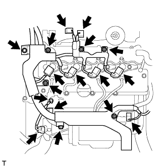
| 2. DISCONNECT ENGINE WIRE |
|
Disconnect the vacuum regulating valve connector.
Disconnect the vacuum switching valve connector.
Disconnect the 4 injector connectors.
Remove the grommet and nut, and disconnect the glow plug wire harness.
Disconnect the fuel pressure sensor connector.
Disconnect the emission control valve wire connector.
Disconnect the pressure discharge valve connector.
Remove the bolt and disconnect the engine wire from the bracket.
Remove the bolt and 5 nuts, and disconnect the engine wire.
| 3. REMOVE EGR VALVE BRACKET |
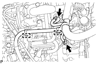 |
Disconnect the 2 connectors and detach the wire harness clamp.
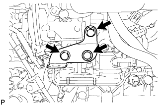 |
Remove the 3 bolts and EGR valve bracket.
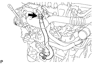
| 4. REMOVE NO. 7 WATER BY-PASS HOSE |
 |
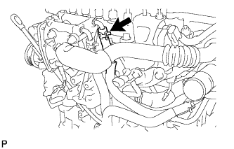
| 5. DISCONNECT NO. 8 WATER BY-PASS HOSE |
 |
| 6. REMOVE NO. 2 EGR PIPE SUB-ASSEMBLY |
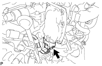 |
Disconnect the electric EGR control valve connector.
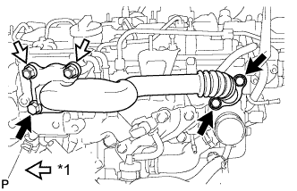 |
Remove the 3 bolts, 2 nuts, No. 2 EGR pipe and 2 gaskets.
| *1 | Nut |
| 7. REMOVE ELECTRIC EGR CONTROL VALVE ASSEMBLY |
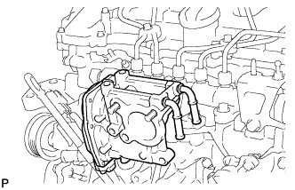 |
Remove the electric EGR control valve and gasket.
| 8. REMOVE FUEL INLET PIPE SUB-ASSEMBLY |
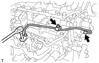 |
Remove the nut and 2 clamps.
Using a 14 mm union nut wrench, remove the fuel inlet pipe.
| 9. REMOVE INJECTION PIPE SUB-ASSEMBLY |
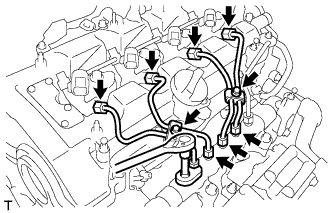 |
Remove the 2 bolts and 4 injection pipe clamps.
Using a 14 mm union nut wrench, loosen the 4 nuts at the common rail end of the injection pipes.
Using a 14 mm union nut wrench, loosen the 4 nuts at the injector end of the injection pipes.
Remove the 4 injection pipes.
| 10. REMOVE COMMON RAIL ASSEMBLY |
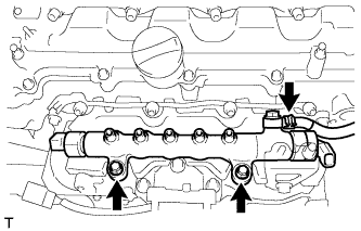 |
Using pliers, grip the claws of the clip and slide the clip to disconnect the fuel hose.
Remove the 2 bolts and common rail.
| 11. REMOVE INTAKE MANIFOLD INSULATOR |
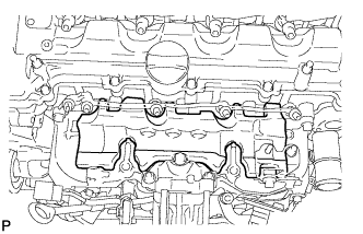 |
Remove the intake manifold insulator from the intake manifold.
| 12. REMOVE ENGINE OIL LEVEL DIPSTICK GUIDE |
Remove the engine oil level dipstick.
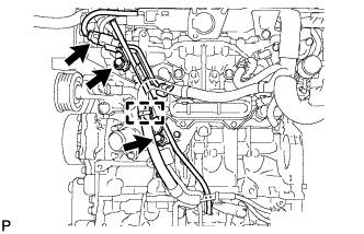 |
Disconnect the connector and detach the wire harness clamp from the engine oil level dipstick guide.
Remove the 2 bolts and engine oil level dipstick guide.
Remove the O-ring from the engine oil level dipstick guide.
| 13. REMOVE DIESEL TURBO PRESSURE SENSOR |
Disconnect the sensor connector.
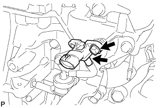 |
Disconnect the vacuum hose.
Remove the bolt and sensor.
| 14. REMOVE NO. 1 GAS FILTER |
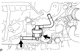 |
Disconnect the vacuum hose.
Remove the No. 1 gas filter from the gas filter bracket.
| 15. REMOVE GAS FILTER BRACKET |
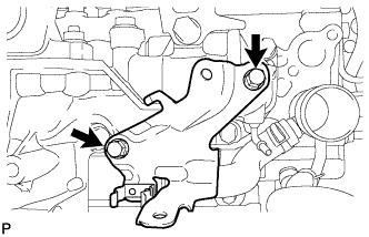 |
Remove the 2 bolts and gas filter bracket.
| 16. REMOVE ENGINE COVER BRACKET |
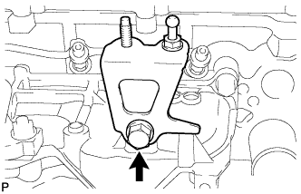 |
Remove the bolt and engine cover bracket.
| 17. REMOVE NO. 2 INTAKE MANIFOLD |
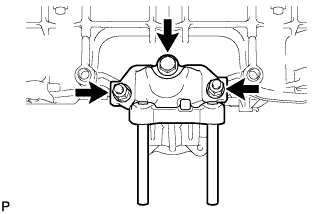 |
Remove the bolt, 2 nuts, No. 2 intake manifold and gasket.
| 18. DISCONNECT NO. 2 VACUUM TRANSMITTING HOSE |
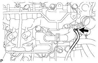 |
Disconnect the No. 2 vacuum transmitting hose from the intake manifold.
| 19. REMOVE INTAKE MANIFOLD |
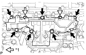 |
Remove the 7 bolts, 2 nuts, intake manifold and gasket.
| *1 | Nut |
| 20. REPLACE STUD BOLT |
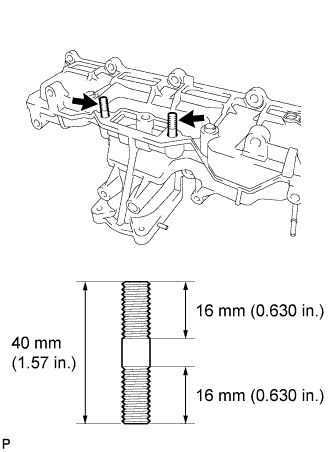 |
Replace the 2 stud bolts.