 |
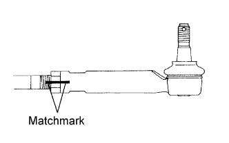
Screw the lock nut and tie rod end on the rack end until the matchmarks are aligned and temporarily tighten the lock nut.
- HINT:
- Fully tighten the lock nut after adjusting toe-in.
STEERING GEAR > INSTALLATION |
| 1. INSTALL TIE ROD END SUB-ASSEMBLY LH |
|
Screw the lock nut and tie rod end on the rack end until the matchmarks are aligned and temporarily tighten the lock nut.
| 2. INSTALL TIE ROD END SUB-ASSEMBLY RH |
| 3. INSTALL STEERING GEAR ASSEMBLY |
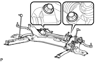 |
Install the steering gear onto the front suspension crossmember with the 2 bolts and 2 nuts.
| 4. INSTALL STEERING INTERMEDIATE SHAFT |
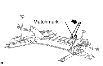 |
Align the matchmarks and install the steering intermediate shaft to the steering gear.
| 5. INSTALL STEERING GEAR HEAT INSULATOR (for 3ZR-FAE RHD) |
Install the heat insulator and bolt to the steering gear.
| 6. INSTALL NO. 1 STEERING COLUMN HOLE COVER SUB-ASSEMBLY |
Install the steering column hole cover to the steering gear with a new clamp.
| 7. INSTALL ENGINE ASSEMBLY WITH TRANSAXLE |
for 1AZ-FE:
Install the engine with transaxle (Click here).
for 2AZ-FE:
Install the engine with transaxle (Click here).
for 2GR-FE:
Install the engine with transaxle (Click here).
for 3ZR-FAE:
Install the engine with transaxle (Click here).
| 8. CONNECT TIE ROD END SUB-ASSEMBLY LH |
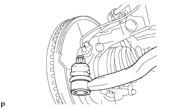 |
Connect the tie rod end to the steering knuckle with the castle nut.
Install a new cotter pin.
| 9. CONNECT TIE ROD END SUB-ASSEMBLY RH |
| 10. INSTALL FRONT WHEELS |
| 11. CONNECT NO. 1 STEERING COLUMN HOLE COVER SUB-ASSEMBLY |
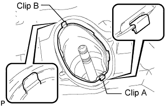 |
Attach clip B to the body portion and connect the No. 1 steering column hole cover to the body portion with clip A.
| 12. CONNECT NO. 2 STEERING INTERMEDIATE SHAFT ASSEMBLY |
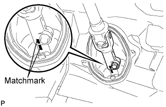 |
Align the matchmarks and install the No. 2 steering intermediate shaft to the steering intermediate shaft.
| 13. INSTALL COLUMN HOLE COVER SILENCER SHEET |
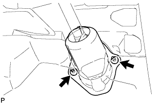 |
Install the silencer sheet with the 2 clips.
Install the floor carpet.
| 14. CONNECT CABLE TO NEGATIVE BATTERY TERMINAL |
| 15. INSPECT AND ADJUST FRONT WHEEL ALIGNMENT |
Inspect and adjust the wheel alignment (Click here).