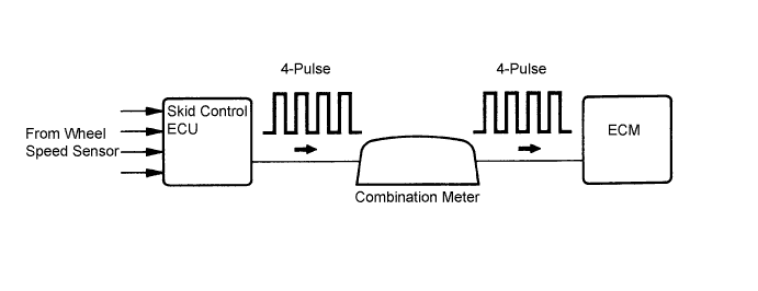
DTC P0500 Vehicle Speed Sensor "A" |
| DTC No. | DTC Detection Condition | Trouble Area |
| P0500 | While vehicle being driven, no vehicle speed sensor signal to ECM. (1 trip detection logic) |
|
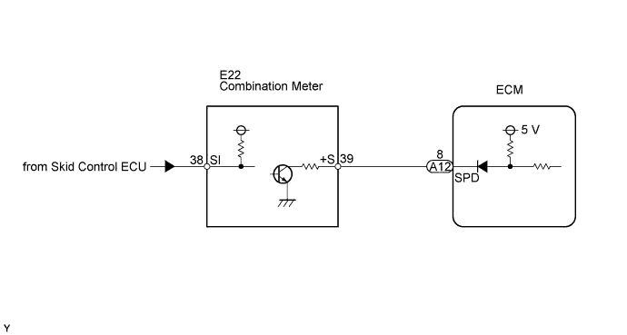
| 1.CHECK OPERATION OF SPEEDOMETER |
Drive the vehicle and check whether the operation of the speedometer in the combination meter is normal.
|
| ||||
| OK | |
 |
| 2.READ VALUE USING INTELLIGENT TESTER (VEHICLE SPEED) |
Connect the intelligent tester to the DLC3.
Turn the ignition switch to the ON position and turn the tester on.
Select the following menu items: Powertrain / Engine and ECT / Data List / Vehicle Speed.
Drive the vehicle.
Read the value displayed on the tester.
|
| ||||
| NG | |
|
| 3.CHECK COMBINATION METER ASSEMBLY (+S VOLTAGE) |
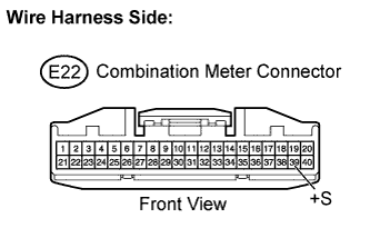 |
Disconnect the combination meter connector.
Turn the ignition switch to the ON position.
Measure the voltage between the terminal of the combination meter and the body ground.
| Tester Connection | Specified Condition |
| +S (E22-39) - Body ground | 9 to 14 V |
Reconnect the combination meter connector.
|
| ||||
| OK | |
|
| 4.CHECK COMBINATION METER ASSEMBLY (SPD SIGNAL WAVEFORM) |
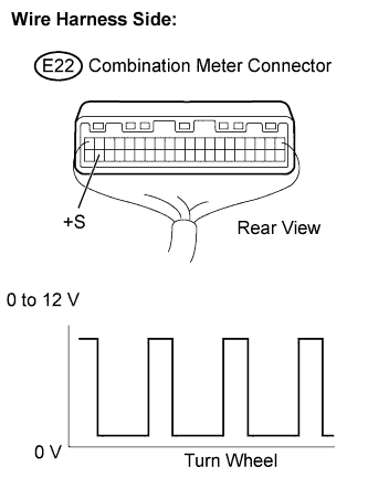 |
Shift the transmission gear selector lever to the neutral position.
Jack up the vehicle.
Turn the ignition switch to the ON position.
Measure the voltage between the terminal of the combination meter and the body ground while the front wheel is turned slowly.
| Tester Connection | Specified Condition |
| +S (E22-39) - Body ground | Voltage generated intermittently |
|
| ||||
| OK | |
|
| 5.CHECK HARNESS AND CONNECTOR (COMBINATION METER ASSEMBLY - ECM) |
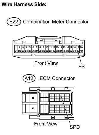 |
Disconnect the combination meter connector.
Disconnect the ECM connector.
Measure the resistance.
| Tester Connection | Specified Condition |
| +S (E22-39) - SPD (A12-8) | Below 1 Ω |
| Tester Connection | Specified Condition |
| +S (E22-39) or SPD (A12-8) - Body ground | 10 kΩ or higher |
Reconnect the combination meter connector.
Reconnect the ECM connector.
|
| ||||
| OK | ||
 | ||
| ||

