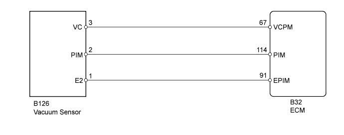
DTC P0105 Manifold Absolute Pressure / Barometric Pressure Circuit |
DTC P0107 Manifold Absolute Pressure / Barometric Pressure Circuit Low Input |
DTC P0108 Manifold Absolute Pressure / Barometric Pressure Circuit High Input |
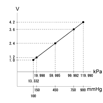
| DTC No. | DTC Detection Condition | Trouble Area |
| P0105 | Either condition is met (1 trip detection logic): (a) The output voltage from the vacuum sensor remains below 0.5 V for 0.5 seconds. (b) The output voltage from the vacuum sensor remains higher than 4.5 V for 0.5 seconds. |
|
| P0107 | The vacuum sensor voltage is below 0.5 V for 0.5 seconds (1 trip detection logic). |
|
| P0108 | The vacuum sensor voltage is higher than 4.5 V for 0.5 seconds (1 trip detection logic). |
|
| MAP | Malfunction |
| Approximately 0 kPa |
|
| 130 kPa or higher |
|
| 1.READ VALUE USING INTELLIGENT TESTER (MANIFOLD ABSOLUTE PRESSURE) |
Connect the intelligent tester to the DLC3.
Turn the ignition switch to ON.
Turn the tester on.
Enter the following menus: Powertrain / Engine and ECT / Data List / MAP.
Read the MAP value.
| Result | Proceed to |
| 0 kPa | A |
| 130 kPa or higher | B |
| Approximately same as atmospheric pressure | C |
|
| ||||
|
| ||||
| A | |
 |
| 2.READ VALUE USING INTELLIGENT TESTER (MANIFOLD ABSOLUTE PRESSURE) |
Connect the intelligent tester to the DLC3.
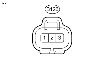 |
Disconnect the vacuum sensor connector.
Turn the ignition switch to ON.
Turn the tester on.
Enter the following menus: Powertrain / Engine and ECT / Data List / MAP.
Check how the "MAP" displayed on the intelligent tester changes compared to the value measured before disconnecting the connector of the vacuum sensor.
| Result | Proceed to |
| Changes (From approximately 0 kPa (0 mmHg, 0 in.Hg) to a value of 130 kPa (975 mmHg, 38.4 in.Hg) or higher) | A |
| Does not change (Approximately 0 kPa (0 mmHg, 0 in.Hg)) | B |
| *1 | Front view of wire harness connector (to Vacuum Sensor) |
Reconnect the vacuum sensor connector.
|
| ||||
| A | ||
 | ||
| ||
| 3.CHECK VACUUM SENSOR (POWER SOURCE) |
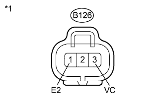 |
Disconnect the vacuum sensor connector.
Measure the voltage according to the value(s) in the table below.
| Tester Connection | Switch Condition | Specified Condition |
| B126-3 (VC) - B126-1 (E2) | Ignition switch ON | 4.5 to 5.5 V |
| *1 | Front view of wire harness connector (to Vacuum Sensor) |
Reconnect the vacuum sensor connector.
|
| ||||
| OK | |
|
| 4.CHECK HARNESS AND CONNECTOR (VACUUM SENSOR - ECM) |
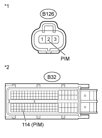 |
Disconnect the vacuum sensor connector.
Disconnect the ECM connector.
Measure the resistance according to the value(s) in the table below.
| Tester Connection | Condition | Specified Condition |
| B126-2 (PIM) - B32-114 (PIM) | Always | Below 1 Ω |
| Tester Connection | Condition | Specified Condition |
| B126-2 (PIM) or B32-114 (PIM) - Body ground | Always | 10 kΩ or higher |
| *1 | Front view of wire harness connector (to Vacuum Sensor) |
| *2 | Front view of wire harness connector (to ECM) |
Reconnect the ECM connector.
Reconnect the vacuum sensor connector.
|
| ||||
| OK | |
|
| 5.REPLACE VACUUM SENSOR |
Replace the vacuum sensor (Click here).
| NEXT | |
|
| 6.CHECK WHETHER DTC OUTPUT RECURS |
Connect the intelligent tester to the DLC3.
Clear the DTCs (Click here).
Turn the ignition switch off.
Turn the ignition switch to ON and turn the tester on.
After the engine is started, race the engine for 1 second.
Enter the following menus: Powertrain / Engine and ECT / DTC.
Read the DTCs.
| Result | Proceed to |
| No DTC is output | A |
| DTCs P0105, P0107 and/or P0108 are output | B |
|
| ||||
| A | ||
| ||
| ||
| 7.CHECK HARNESS AND CONNECTOR (VACUUM SENSOR - ECM) |
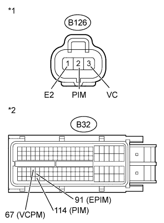 |
Disconnect the vacuum sensor connector.
Disconnect the ECM connector.
Measure the resistance according to the value(s) in the table below.
| Tester Connection | Condition | Specified Condition |
| B126-2 (PIM) - B32-114 (PIM) | Always | Below 1 Ω |
| B126-3 (VC) - B32-67 (VCPM) | Always | Below 1 Ω |
| B126-1 (E2) - B32-91 (EPIM) | Always | Below 1 Ω |
| Tester Connection | Condition | Specified Condition |
| B126-2 (PIM) or B32-114 (PIM) - Body ground | Always | 10 kΩ or higher |
| B126-3 (VC) or B32-67 (VCPM) - Body ground | Always | 10 kΩ or higher |
| B126-1 (E2) or B32-91 (EPIM) - Body ground | Always | 10 kΩ or higher |
| *1 | Front view of wire harness connector (to Vacuum Sensor) |
| *2 | Front view of wire harness connector (to ECM) |
Reconnect the ECM connector.
Reconnect the vacuum sensor connector.
|
| ||||
| OK | ||
| ||
| ||

