 |
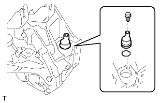
Coat a new O-ring with gear oil.
MANUAL TRANSAXLE ASSEMBLY > INSTALLATION |
| 1. INSTALL SPEEDOMETER DRIVEN HOLE COVER SUB-ASSEMBLY |
|
Coat a new O-ring with gear oil.
Install the O-ring to the speedometer driven hole cover sub-assembly.
Install the speedometer driven hole cover sub-assembly to the transaxle case with the bolt.
| 2. INSTALL CLUTCH RELEASE WITH BEARING CYLINDER ASSEMBLY |
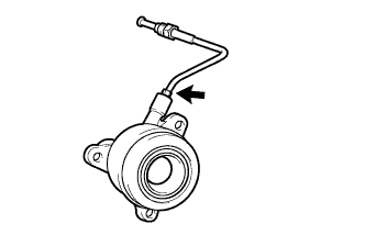 |
Temporarily install the clutch release cylinder to bleeder tube to a new clutch release with bearing cylinder assembly.
Clean and degrease all installation surfaces for the clutch release with bearing cylinder assembly.
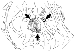 |
Install the clutch release with bearing cylinder assembly with 3 new bolts.
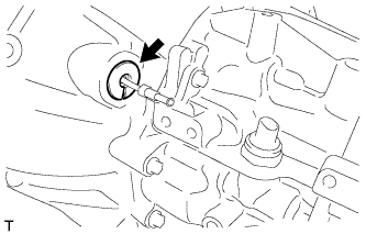 |
Install the clutch tube boot to the manual transaxle assembly.
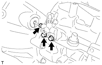 |
Temporarily install the clutch release cylinder to bleeder tube to the clutch release bleeder sub-assembly.
Temporarily install the clutch release bleeder sub-assembly with the 2 bolts.
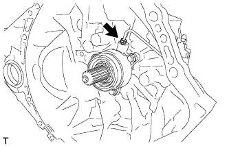 |
Using a union nut wrench, install the clutch release cylinder to bleeder tube to the clutch release with bearing cylinder assembly.
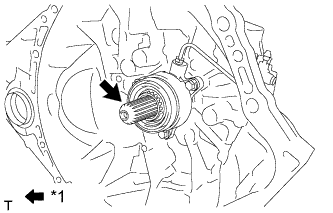 |
Apply clutch spline grease to the input shaft spline.
| *1 | Clutch Spline Grease |
| 3. REMOVE CLUTCH RELEASE BLEEDER SUB-ASSEMBLY |
|
Separate the clutch release cylinder to bleeder tube from the clutch release bleeder sub-assembly.
Remove the 2 bolts and clutch release bleeder sub-assembly.
| 4. INSPECT CLUTCH PIPE LINE |
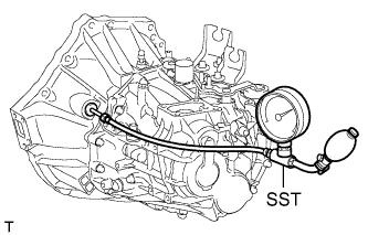 |
Using SST, apply a pressure of 100 kPa (1.0 kgf/cm2, 15 psi) to the clutch pipe location shown in the illustration and confirm that pressure is maintained for 15 seconds or more.
| 5. INSTALL CLUTCH RELEASE BLEEDER SUB-ASSEMBLY |
|
Temporarily install the clutch release cylinder to bleeder tube to the clutch release bleeder sub-assembly.
Install the clutch release bleeder sub-assembly with the 2 bolts.
Using a union nut wrench, install the clutch release cylinder to bleeder tube.
| 6. INSTALL CLUTCH FLEXIBLE HOSE BRACKET |
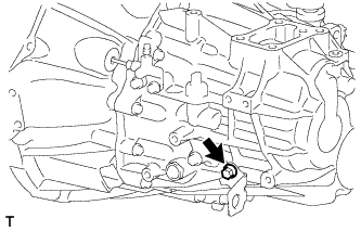 |
Install the clutch flexible hose bracket to the manual transaxle with the bolt.
| 7. INSTALL CLUTCH ORIFICE ASSEMBLY |
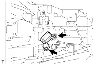 |
Install the clutch orifice assembly with the 2 bolts.
| 8. INSTALL CLUTCH RELEASE CYLINDER TO ACCUMULATOR TUBE |
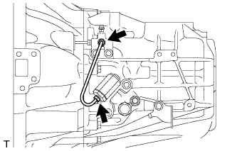 |
Using a union nut wrench, install the clutch release cylinder to accumulator tube.
| 9. INSTALL ORIFICE TO FLEXIBLE HOSE TUBE |
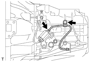 |
Temporarily tighten the orifice to flexible hose tube onto the clutch orifice assembly.
Install the orifice to flexible hose tube with the bolt.
Using a union nut wrench, install the orifice to flexible hose tube.
| 10. INSTALL REAR ENGINE MOUNTING BRACKET |
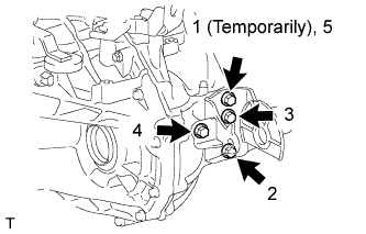 |
Install the rear engine mounting bracket with the 4 bolts.
| 11. INSTALL ENGINE MOUNTING BRACKET LH |
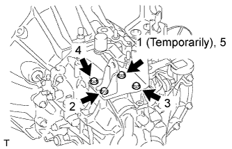 |
Apply sealant to the 4 bolts.
Install the engine mounting bracket LH with the 4 bolts.
| 12. INSTALL FRONT ENGINE MOUNTING BRACKET |
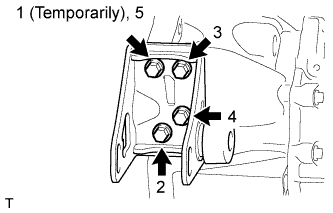 |
Install the front engine mounting bracket with the 4 bolts.
| 13. INSTALL MANUAL TRANSAXLE ASSEMBLY |
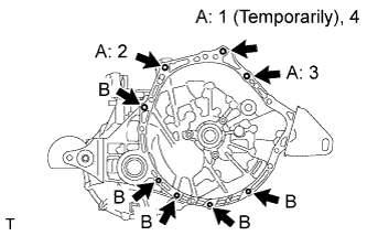 |
Align the input shaft with the clutch disc and install the manual transaxle to the engine.
Install the 3 bolts labeled A in the order shown in the illustration, and then install the 5 bolts labeled B.
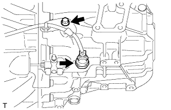 |
Connect the back-up light switch connector and install the engine wire to the manual transaxle with the bolt.
| 14. INSTALL ENGINE WIRE |
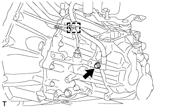 |
Install the bolt, clamp and engine wire to the manual transaxle.
| 15. INSTALL STARTER ASSEMBLY |
| 16. INSTALL ENGINE ASSEMBLY WITH TRANSAXLE |
Install the engine assembly with transaxle (Click here).