LOWER INSTRUMENT PANEL > REMOVAL |
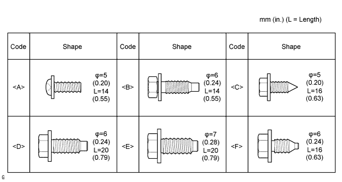
| 1. TABLE OF BOLT, SCREW AND NUT |
| 2. DISCONNECT CABLE FROM NEGATIVE BATTERY TERMINAL |
| 3. REMOVE INSTRUMENT PANEL SUB-ASSEMBLY |
Remove the instrument panel (Click here).
| 4. REMOVE STEERING COLUMN COVER |
for LHD:
Remove the steering column cover .
for RHD:
Remove the steering column cover .
| 5. REMOVE SPIRAL CABLE SUB-ASSEMBLY |
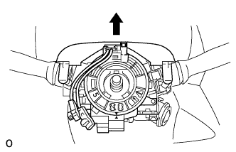 |
Rise the steering column cover (upper).
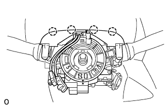 |
Detach the 4 clips and remove the column cover (upper).
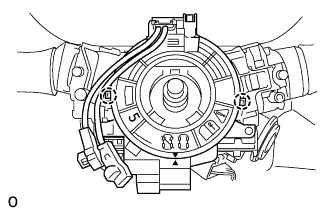 |
Detach the 3 claws and remove the spiral cable.
| 6. REMOVE COMBINATION SWITCH ASSEMBLY |
Disconnect the all the connectors from the spiral cable.
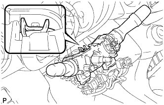 |
Detach the clamp shown in the illustration and remove the combination switch from the steering column.
| 7. REMOVE HEATER CONTROL SUB-ASSEMBLY (for Automatic Air Conditioning System) |
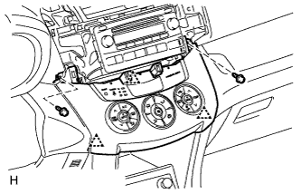 |
Remove the 2 screws.
Using a screwdriver, detach the 3 clips.
Connect the connectors and remove the air conditioning control.
| 8. REMOVE HEATER CONTROL SUB-ASSEMBLY (for Manual Air Conditioning System) |
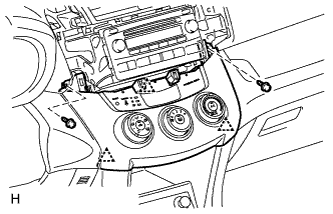 |
Remove the 2 screws.
Using a screwdriver, detach the 3 clips.
Disconnect the connectors and remove the air conditioning control.
| 9. REMOVE SHIFT LEVER KNOB SUB-ASSEMBLY |
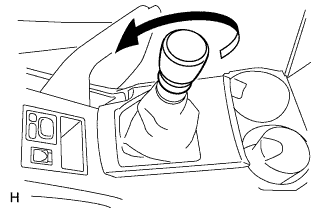 |
for Manual Transaxle:
Twist the shift lever knob in the direction indicated by the arrow and remove it.
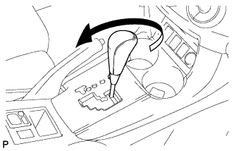 |
for Automatic Transaxle:
Twist the shift lever knob in the direction indicated by the arrow and remove it.
| 10. REMOVE NO. 1 CONSOLE UPPER PANEL GARNISH |
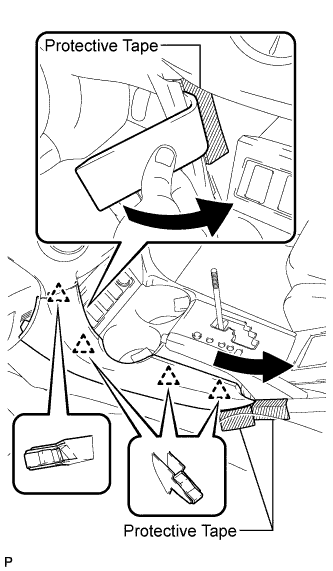 |
Place protective tape as shown in the illustration.
Using a moulding remover, detach the 4 clips and remove the upper panel garnish.
| 11. REMOVE NO. 2 CONSOLE UPPER PANEL GARNISH |
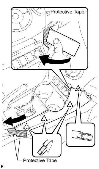 |
Place protective tape as shown in the illustration.
Using a moulding remover, detach the 4 clips and remove the upper panel garnish.
| 12. REMOVE UPPER CONSOLE PANEL SUB-ASSEMBLY (for Manual Transaxle) |
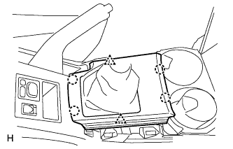 |
Using a screwdriver, detach the 2 clips and 4 claws, and then remove the upper console panel.
| 13. REMOVE FLOOR SHIFT POSITION INDICATOR HOUSING SUB-ASSEMBLY (for Automatic Transaxle) |
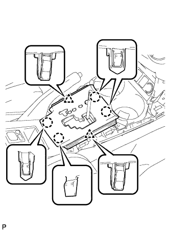 |
Using a screwdriver, detach the 2 clips and 4 claws, and then remove the floor shift position indicator housing.
Disconnect the connector.
| 14. REMOVE SWITCH BASE |
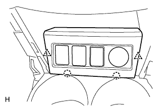 |
Detach the 2 clips and 2 claws.
Disconnect the connectors and remove the switch base.
| 15. REMOVE CONSOLE CUP HOLDER BOX |
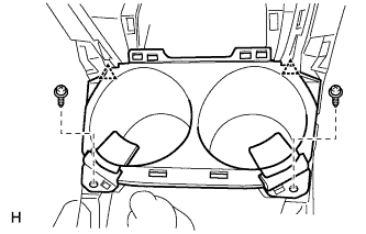 |
Remove the 2 screws.
Detach the 2 clips and remove the cup holder box.
| 16. REMOVE UPPER REAR CONSOLE PANEL SUB-ASSEMBLY |
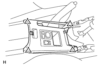 |
Using a screwdriver, detach the 4 clips.
Disconnect the connectors and remove the upper rear console panel.
| 17. REMOVE CONSOLE REAR END PANEL |
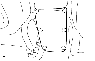 |
Using a screwdriver, detach the 6 claws and remove the console rear end panel.
| 18. REMOVE NO. 1 INSTRUMENT PANEL BRACKET COVER INNER LH |
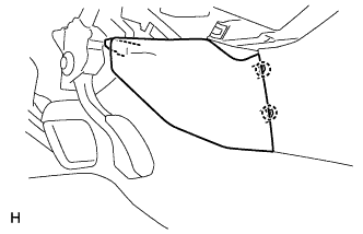 |
Detach the 2 claws and remove the instrument panel bracket cover.
| 19. REMOVE NO. 1 INSTRUMENT PANEL BRACKET COVER INNER RH |
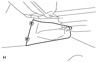 |
Detach the 2 claws and remove the instrument panel bracket cover.
| 20. REMOVE CONSOLE BOX CARPET |
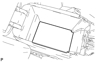 |
Remove the console box carpet.
| 21. REMOVE REAR CONSOLE BOX SUB-ASSEMBLY |
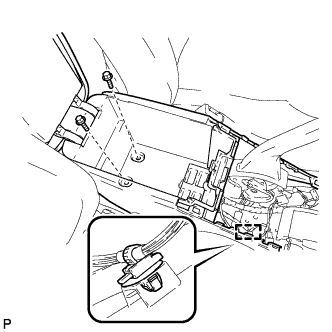 |
Remove the 2 bolts and detach the wire harness clamp.
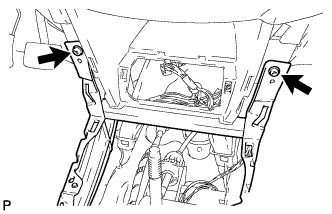 |
Remove the 2 screws.
Disconnect the connector and remove the rear console box.
| 22. REMOVE NO. 1 INSTRUMENT PANEL UNDER COVER SUB-ASSEMBLY |
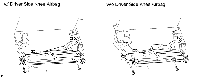
Remove the 2 screws.
Detach the 2 claws and 2 guides and remove the cover.
| 23. REMOVE DRIVER SIDE KNEE AIRBAG ASSEMBLY (w/ Driver Side Knee Airbag) |
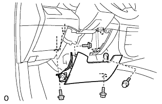 |
Remove the 4 bolts and driver side knee airbag.
Disconnect the connector.
| 24. REMOVE LOWER INSTRUMENT PANEL FINISH PANEL (w/o Driver Side Knee Airbag) |
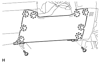 |
Remove the 2 screws.
Using a screwdriver, detach the 8 claws and remove the lower instrument panel finish panel.
| 25. REMOVE NO. 2 INSTRUMENT PANEL UNDER COVER SUB-ASSEMBLY |
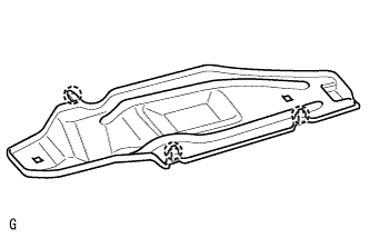 |
Detach the 3 claws and remove the instrument panel under cover.
| 26. REMOVE FRONT DOOR SCUFF PLATE LH |
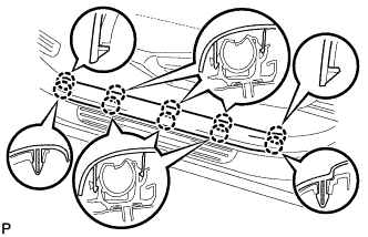 |
Using a screwdriver, detach the 10 claws and remove the scuff plate.
| 27. REMOVE FRONT DOOR SCUFF PLATE RH |
| 28. REMOVE COWL SIDE TRIM BOARD LH |
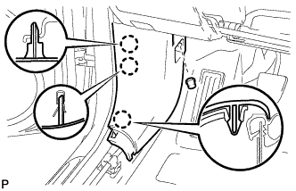 |
Remove the cap nut.
Using a screwdriver, detach the 3 claws and remove the trim board.
| 29. REMOVE COWL SIDE TRIM BOARD RH |
| 30. REMOVE NO. 1 SWITCH HOLE BASE |
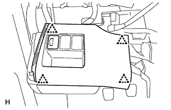 |
Using a screwdriver, detach the 4 clips.
Disconnect the connectors and remove the switch hole base.
| 31. REMOVE INSTRUMENT PANEL BOX |
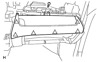 |
Remove the screw.
Using a screwdriver, detach the 6 clips and remove the instrument panel box.
| 32. REMOVE POWER STEERING ECU ASSEMBLY |
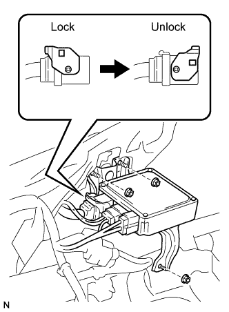 |
Disconnect the connectors.
Remove the 3 nuts and ECU.
| 33. REMOVE HOOD LOCK CONTROL LEVER SUB-ASSEMBLY |
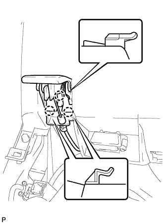 |
Detach the 3 claws and remove the hood lock control lever.
| 34. REMOVE NO. 6 HEATER TO REGISTER DUCT ASSEMBLY (w/ Cool Box) |
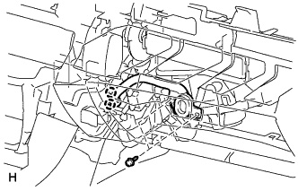 |
Remove the 2 screws.
Detach the 2 claws and remove the duct.
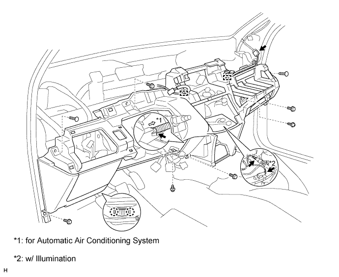
| 35. REMOVE LOWER INSTRUMENT PANEL |
Remove the 4 bolts, 2 screws and 2 clips.
Detach the claws and remove the DLC3.
for Automatic Air Conditioning System:
Disconnect the connector and remove the cooler thermistor hose.
w/ Illumination:
Disconnect the connectors.
Disconnect the connectors, detach the clamps and remove the lower instrument panel.