DIFFERENTIAL OIL SEAL > REPLACEMENT |
| 1. REMOVE FRONT DRIVE SHAFT ASSEMBLY |
Remove the front drive shaft assembly (Click here).
| 2. REMOVE TRANSMISSION CASE OIL SEAL |
|
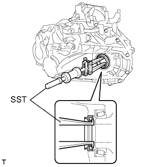
Using SST, remove the transmission case oil seal.
| 3. REMOVE MANUAL TRANSAXLE ASSEMBLY |
Remove the manual transaxle assembly (Click here).
| 4. REMOVE CLUTCH RELEASE BLEEDER SUB-ASSEMBLY |
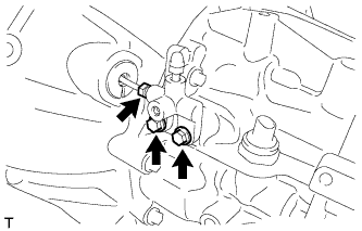 |
Using a union nut wrench, separate the clutch release bleeder sub-assembly from the clutch release cylinder to bleeder tube.
Remove the 2 bolts and clutch release bleeder sub-assembly from the manual transaxle assembly.
| 5. REMOVE CLUTCH RELEASE WITH BEARING CYLINDER ASSEMBLY |
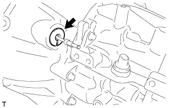 |
Remove the clutch tube boot from the manual transaxle assembly.
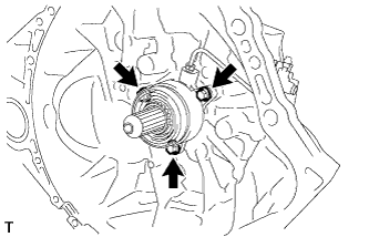 |
Remove the 3 bolts and clutch release with bearing cylinder assembly and clutch release cylinder to bleeder tube.
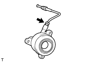 |
Using a union nut wrench, remove the clutch release cylinder to bleeder tube from the clutch release with bearing cylinder assembly.
| 6. SECURE MANUAL TRANSAXLE ASSEMBLY |
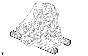 |
Place the manual transaxle on wooden blocks.
| 7. REMOVE REVERSE IDLER GEAR SHAFT BOLT |
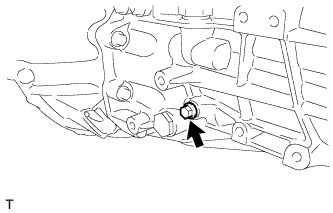 |
Remove the reverse idler gear shaft bolt and gasket from the manual transmission case.
| 8. REMOVE MANUAL TRANSMISSION CASE |
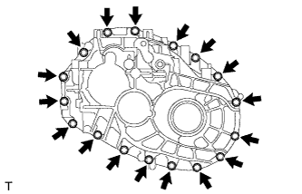 |
Remove the 17 bolts.
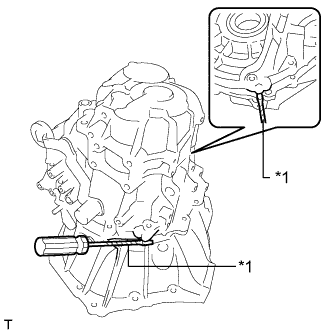 |
Using a screwdriver with its tip wrapped with protective tape, separate the manual transmission case from the front transaxle case.
| *1 | Protective Tape |
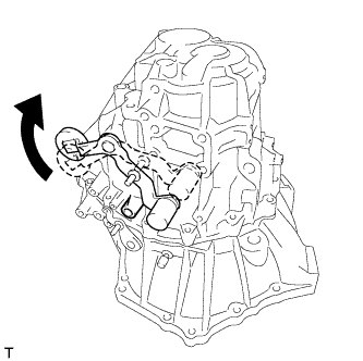 |
Turn the outer No. 1 shift lever clockwise until it comes into contact with the boss.
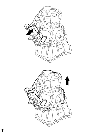 |
Push the outer No. 1 shift lever and remove the manual transmission case.
| 9. REMOVE REVERSE IDLER GEAR SUB-ASSEMBLY |
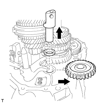 |
Remove the reverse idler gear, thrust washer and reverse idler gear shaft from the front transaxle case.
| 10. REMOVE REVERSE SHIFT FORK SHAFT ASSEMBLY |
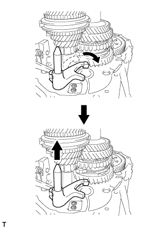 |
Turn the reverse shift fork shaft clockwise and remove it from the front transaxle case.
| 11. REMOVE REVERSE SHIFT FORK |
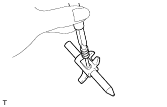 |
Using a 5 mm pin punch and hammer, tap out the reverse shift fork slotted spring pin.
Remove the reverse shift fork from the reverse shift fork shaft.
| 12. REMOVE REVERSE SHIFT ARM BRACKET ASSEMBLY |
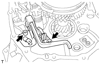 |
Using a 6 mm hexagon socket wrench, remove the 2 bolts and reverse shift arm bracket from the front transaxle case.
| 13. REMOVE SHIFT AND SELECT LEVER SHAFT ASSEMBLY |
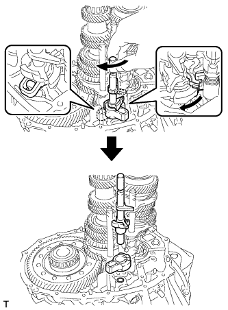 |
Turn the shift and select lever shaft clockwise and remove it from the front transaxle case.
| 14. REMOVE INPUT SHAFT ASSEMBLY |
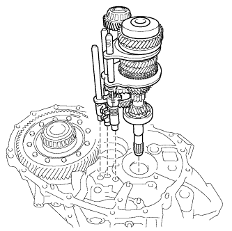 |
Remove the input shaft assembly, output shaft assembly and 2 gear shift fork shaft assemblies from the front transaxle case.
Remove the output shaft assembly together with the No. 1 gear shift fork shaft assembly from the input shaft assembly.
Remove the No. 1 gear shift fork shaft assembly from the output shaft assembly.
Remove the No. 2 gear shift fork shaft assemblies from the input shaft assembly.
| 15. REMOVE DIFFERENTIAL CASE ASSEMBLY |
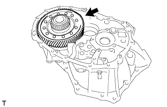 |
Remove the differential case from the front transaxle case.
| 16. REMOVE FRONT DIFFERENTIAL CASE OIL SEAL |
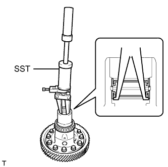 |
Using SST, remove the front differential case oil seal from the front differential case.
| 17. REMOVE FRONT TRANSAXLE CASE OIL SEAL |
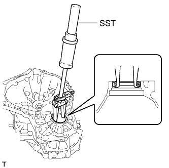 |
Using SST, remove the front transaxle case oil seal.
| 18. INSTALL FRONT TRANSAXLE CASE OIL SEAL |
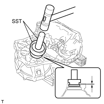 |
Coat the lip of a new oil seal with MP grease.
Using SST and a hammer, tap in the front transaxle case oil seal to the front transaxle case.
| 19. INSTALL FRONT DIFFERENTIAL CASE OIL SEAL |
Coat the lip of a new oil seal with MP grease.
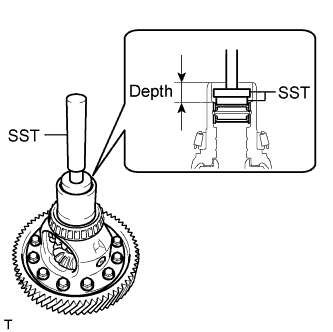 |
Using SST and a hammer, tap in a new front differential case oil seal to the front differential case.
| 20. ADJUST OUTPUT SHAFT BEARING PRELOAD |
|
Coat the differential case assembly with gear oil and install it to the front transaxle case.
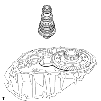 |
Coat the output shaft assembly with gear oil and install it to the front transaxle case.
|
Install the manual transmission case with the 17 bolts.
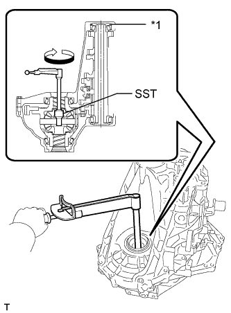 |
Using SST and a torque wrench, turn the differential case assembly clockwise and counterclockwise 2 or 3 times to allow the bearings to settle.
Using SST and a torque wrench, measure the preload (value A). Calculate the rear output shaft bearing preload using the following formula.
| *1 | Bearing Shim |
| Mark | Specified Condition | Mark | Specified Condition |
| A | 1.30 mm (0.511 in.) | P | 1.95 mm (0.768 in.) |
| B | 1.35 mm (0.531 in.) | Q | 2.00 mm (0.787 in.) |
| C | 1.40 mm (0.551 in.) | R | 2.05 mm (0.807 in.) |
| D | 1.45 mm (0.571 in.) | S | 2.10 mm (0.827 in.) |
| E | 1.50 mm (0.591 in.) | T | 2.15 mm (0.846 in.) |
| F | 1.55 mm (0.610 in.) | U | 2.20 mm (0.866 in.) |
| G | 1.60 mm (0.630 in.) | V | 2.25 mm (0.886 in.) |
| H | 1.65 mm (0.650 in.) | W | 2.30 mm (0.906 in.) |
| J | 1.70 mm (0.669 in.) | X | 2.35 mm (0.925 in.) |
| K | 1.75 mm (0.689 in.) | Y | 2.40 mm (0.945 in.) |
| L | 1.80 mm (0.709 in.) | Z | 2.45 mm (0.965 in.) |
| M | 1.85 mm (0.728 in.) | 1 | 2.50 mm (0.984 in.) |
| N | 1.90 mm (0.748 in.) | - | - |
Remove the 17 bolts and manual transmission case.
Remove the output shaft assembly from the front transaxle case.
Remove the differential case from the front transaxle case.
Replace the installed rear output shaft bearing shim with the one selected above.
| 21. INSTALL DIFFERENTIAL CASE ASSEMBLY |
|
Coat the differential case tapered roller bearing with gear oil and install it to the front transaxle case.
| 22. INSTALL INPUT SHAFT ASSEMBLY |
Apply gear oil to all sliding and rotating parts.
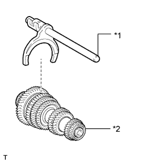 |
Coat the No. 1 gear shift fork shaft with gear oil and install it onto the output shaft assembly.
| *1 | No. 1 Gear Shift Fork Shaft |
| *2 | Output Shaft |
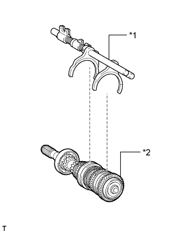 |
Coat the No. 2 gear shift fork shaft with gear oil and install it onto the input shaft assembly.
| *1 | No. 2 Gear Shift Fork Shaft |
| *2 | Input shaft |
Temporarily install the output shaft with No. 1 gear shift fork shaft to the input shaft assembly, and tie them with a rope or string.
|
Install the input shaft assembly, output shaft assembly and 2 gear shift fork shaft assemblies to the front transaxle case.
| 23. INSTALL SHIFT AND SELECT LEVER SHAFT ASSEMBLY |
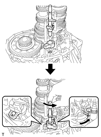 |
Install the shift interlock plate and shift and select lever shaft assembly to the front transaxle case, and then turn them counterclockwise.
| 24. INSTALL REVERSE SHIFT ARM BRACKET ASSEMBLY |
|
Coat the threads of the 2 bolts with adhesive, and then install the reverse shift arm bracket with the 2 bolts.
| 25. INSTALL REVERSE SHIFT FORK |
|
Using a 5 mm pin punch and a hammer, install the reverse shift fork slotted pin onto the reverse shift fork shaft.
| 26. INSTALL REVERSE SHIFT FORK SHAFT ASSEMBLY |
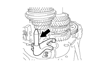 |
Coat the reverse shift fork shaft assembly with gear oil and install it onto the front transaxle case.
| 27. INSTALL REVERSE IDLER GEAR SUB-ASSEMBLY |
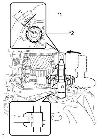 |
Coat the reverse idler gear sub-assembly, thrust washer and reverse idler gear shaft with gear oil, and install them as shown in the illustration.
| *1 | Case Hole |
| *2 | I-groove mark of the reverse idler gear shaft |
| 28. INSTALL MANUAL TRANSMISSION CASE |
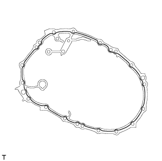 |
Apply seal packing to the manual transmission case as shown in the illustration.
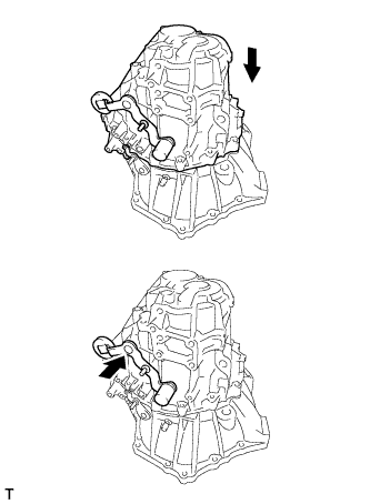 |
Push the outer No. 1 shift lever and install the manual transmission case.
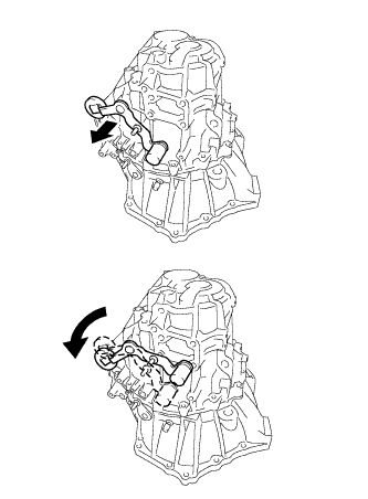 |
Turn the outer No. 1 shift lever counterclockwise and then pull it.
|
Install the manual transmission case with the 17 bolts.
| 29. INSTALL REVERSE IDLER GEAR SHAFT BOLT |
|
Install a new gasket and the reverse idler gear shaft bolt to the manual transmission case.
| 30. INSTALL CLUTCH RELEASE WITH BEARING CYLINDER ASSEMBLY |
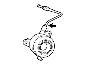 |
Temporarily install the clutch release cylinder to bleeder tube to a new clutch release with bearing cylinder assembly.
Clean and degrease all installation surfaces for the clutch release with bearing cylinder assembly.
|
Install the clutch release with bearing cylinder assembly with 3 new bolts.
|
Install the clutch tube boot to the manual transaxle assembly.
|
Temporarily install the clutch release cylinder to bleeder tube to the clutch release bleeder sub-assembly.
Temporarily install the clutch release bleeder sub-assembly with the 2 bolts.
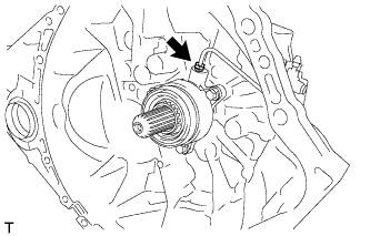 |
Using a union nut wrench, install the clutch release cylinder to bleeder tube to the clutch release with bearing cylinder assembly.
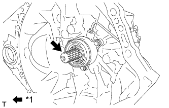 |
Apply clutch spline grease to the input shaft spline.
| *1 | Clutch Spline Grease |
| 31. REMOVE CLUTCH RELEASE BLEEDER SUB-ASSEMBLY |
|
Separate the clutch release cylinder to bleeder tube from the clutch release bleeder sub-assembly.
Remove the 2 bolts and clutch release bleeder sub-assembly.
| 32. INSPECT CLUTCH PIPE LINE |
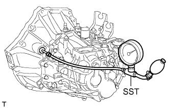 |
Using SST, apply a pressure of 100 kPa (1.0 kgf/cm2, 15 psi) to the clutch pipe location shown in the illustration and confirm that pressure is maintained for 15 seconds or more.
| 33. INSTALL CLUTCH RELEASE BLEEDER SUB-ASSEMBLY |
|
Temporarily install the clutch release cylinder to bleeder tube to the clutch release bleeder sub-assembly.
Install the clutch release bleeder sub-assembly with the 2 bolts.
Using a union nut wrench, install the clutch release cylinder to bleeder tube.
| 34. INSTALL MANUAL TRANSAXLE ASSEMBLY |
the manual transaxle assembly (Click here).
| 35. INSTALL TRANSMISSION CASE OIL SEAL |
Coat the lip of a new oil seal with MP grease.
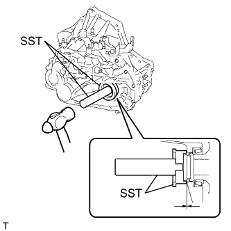 |
Using SST and a hammer, tap in the transmission case oil seal to the manual transmission case.
| 36. INSTALL FRONT DRIVE SHAFT ASSEMBLY |
Install the front drive shaft assembly (Click here).
| 37. INSPECT FOR OIL LEAK |