 |
Connect the connectors.
HEADLIGHT ASSEMBLY (w/ Hood Moulding) > INSTALLATION |
| 1. INSTALL HEADLIGHT ASSEMBLY LH |
|
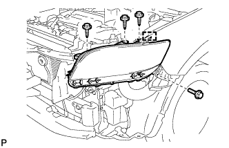
Connect the connectors.
Attach the clamp to install the headlight.
Install the headlight with the bolt and 3 screws.
| 2. INSTALL FRONT BUMPER COVER |
Install the front bumper cover (Click here).
| 3. PREPARATION FOR HEADLIGHT AIMING ADJUSTMENT |
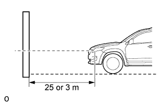 |
Prepare the vehicle:
Prepare a piece of thick white paper approximately 2 m (6.56 ft.) (height) x 4 m (13.1 ft.) (width) to use as a screen.
Draw a vertical line down the center of the screen (V line).
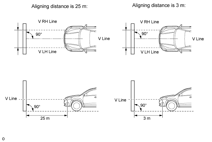
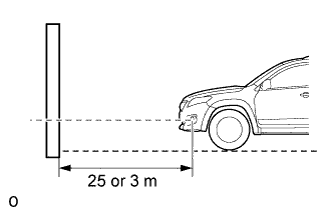
Set the screen as shown in the illustration.
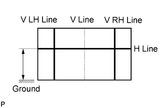 |
Draw base lines (H, V LH, and V RH Lines) on the screen as shown in the illustration.
H Line (Headlight):
Draw a horizontal line across the screen so that it passes through the center marks. The H line should be at the same height as the headlight bulb center marks of the low beam headlights.
V LH Line, V RH Line (Center mark position of the left-hand (LH) and right-hand (RH) headlights):
Draw two vertical lines so that they intersect the H line at each center mark (aligned with the center of the low beam headlight bulbs).
| 4. INSPECT HEADLIGHT AIMING |
Cover the headlight or disconnect the connector of the headlight on the opposite side to prevent light from the headlight that is not being inspected from affecting the headlight aiming.
Start the engine.
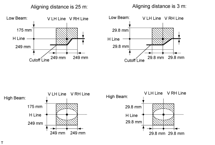
Turn on the headlight and check if the cutoff line matches the preferred cutoff line in the following illustration.
| 5. ADJUST HEADLIGHT AIMING |
Headlight high beam.
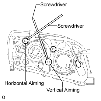 |
Using a screwdriver, adjust the aim.
Adjust the aim of each headlight to the specified range by turning each aiming screw with a screwdriver.
Headlight low beam.
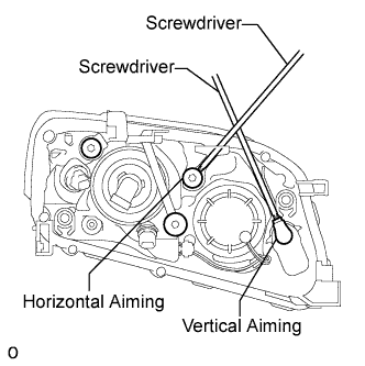 |
Using a screwdriver, adjust the aim.
Adjust the aim of each headlight to the specified range by turning each aiming screw with a screwdriver.
| 6. PREPARATION FOR FOG LIGHT AIMING |
 |
Prepare the vehicle:
Prepare a piece of thick white paper approximately 2.0 m (6.56 ft.) (height) x 4.0 m (13.1 ft.) (width) to use as a screen.
Draw a vertical line down the center of the screen (V line).
Set the screen as shown in the illustration.
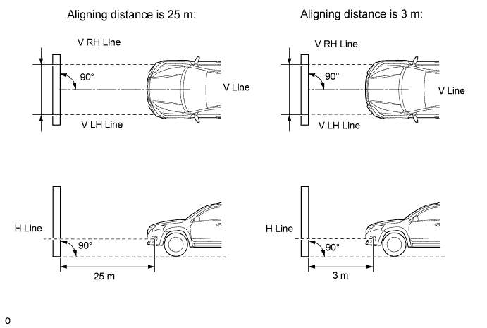
|
Draw base lines (H, V LH, and V RH lines) on the screen as shown in the illustration.
H line (Fog light height):
Draw a horizontal line across the screen so that it passes through the center marks. The H line should be at the same height as the fog light bulb center marks of the fog lights.
V LH Line, V RH Line (Center mark position of left-hand (LH) and right-hand (RH) fog lights):
Draw two vertical lines so that they intersect the H line at each center mark.
| 7. INSPECT FOG LIGHT AIMING |
Cover the fog light or disconnect the connector of the fog light on the opposite side to prevent light from the fog light that is not being inspected from affecting the fog light aiming inspection.
Start the engine.
Turn on the fog light and check if the cutoff line falls within the specified area in the following illustration.
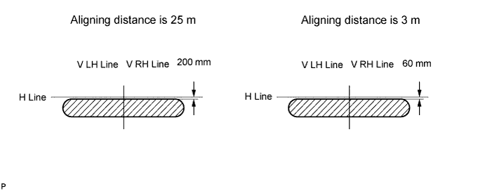
| 8. ADJUST FOG LIGHT AIMING |
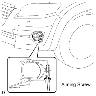 |
Adjust the aim vertically.
Adjust the aim of each fog light to the specified range by turning the aiming screw with a screwdriver.